INSTALLATION Manual Vehicle Application Ford (6.0L) ‘03-’07 GM (6.6.0 L) ‘01-’07 Dodge (5.
INTRODUCTION Introduction TROUBLESHOOTING: Parts Description If you have questions during the installation of this product, please visit www.bullydog.com/Product_Updates.php. The latest version of these instructions can be found at the same location. Please review the Troubleshooting section on page 66 before calling technical support to cover most common issues.Technical support is available by calling 866bullydog (866-285-5936). TABLE OF CONTENTS INTRODUCTION...........................................
INTRODUCTION OPERATING INSTRUCTIONS (continued)................................................................. pgs. 28-44 Introduction Section 4: Exploring the Menu System................................................................ pg. 35-58 Main menu description/navigation............................................................................................................... 35 Change vehicle......................................................................................................
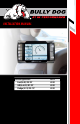
INTRODUCTION Introduction INTRODUCTION Parts Description The PMT is the most advanced vehicle downloader, controller, monitor and gauge in a single unit. This product is engineered to provide the most benefits and the greatest features of any combination of engine performance and monitoring enhancements in the automotive aftermarket. This product is easy to install on any applicable vehicle; all operations of the PMT take place in-cab and feature on-the-fly adjustments.
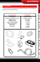
BILL OF MATERIALS Introduction Bill of Materials The list below includes by name the major parts included in your PMT package. The tools list indicates all of the tools necessary to complete the PMT install.
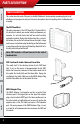
PARTS DESCRIPTION Introduction Parts description This section describes each of the parts in the Bill of Materials, the descriptions provide a physical set of attributes and a purpose for each part. The parts descriptions also list everything that is included in each assembly. Parts Description The PMT Head Unit The main component is the PMT Head Unit. The Head Unit is the interface in which you control vehicle performance parameters.
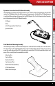
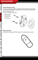
PARTS DESCRIPTION Introduction Pyrometer Connection Head (PCH) Board Assembly The PCH Board or Pyrometer Connection Head serves as a dock to connect the pyrometers into the PMT system. The PCH Board includes the ability to connect two pyrometers. Attached to the PCH Board housing is a cable with four pin plug which connects to the OBDII Adapter Plug. The list below includes all separate parts that make up the entire PCH Board Assembly.
PARTS DESCRIPTION Introduction Custom A-Pillar Mount Assembly This mounting assembly enables the PMT to be mounted on the Custom A-Pillar Pod on the driver’s side of the vehicle. Using this mounting style does require that a Custom A-Pillar Pod be purchased from Bully Dog, but it also offers the cleanest install.
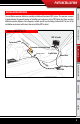
PMT INSTALLATION Introduction Installation Overview The installation overview illustrates a totally installed and functional PMT system. This overview is meant to help reference the general location of installed parts and pieces of the PMT. Notice that there are three different overview diagrams. Each diagram is vehicle specific; one for Dodge, Ford and GM. The rest of the installation instructions Installation will instruct how to install the PMT in detail.
PMT INSTALLATION Introduction FORD POWER STROKE ‘03-07 Parts Description Pyrometer Connection Head PMT & Cradle Fire wall gromme t Power Wire Cradle Cable fuse box PMT Installation Pyrometer Probe (to exhaust manifold) OBDII Port PCH Cable OBDII Adapter Plug Operating Instructions GM DURAMAX ‘02-’07 PMT & Cradle Pyromete r Connec tion Head Internet Updates Power Wire fuse box all Fire w met grom Cable Cradle Pyromete r Probe ) anifold aust m h (to ex ble PCH Ca ort OBDII P App
PMT INSTALLATION These installation instructions are split into five sections. Each section provides a comprehensive description of installation for all vehicle applications.
PMT INSTALLATION Introduction Parts Description Custom A-Pillar mounting We recommend the Custom A-Pillar mounting style, because it makes for the best looking, most convenient and least intrusive mounting style. The Custom A-Pillar mounting style does require that a Custom A-Pillar Pod be purchased from Bully Dog; see part numbers and vehicle applications for a Custom A-Pillar Pod in the appendix.
PMT INSTALLATION Introduction 2. With all assembly pieces gathered, refer to the Pillar Pod Mount Assembly Diagram for a visual reference on how the assembly fits together. Steps 3 through 6 explain how to assemble the pieces, the A Pillar Mount Diagram shows what the assembled mounting style looks like. 3. Insert the ball that is on the back of the cradle into the lower hole on the front of the Front Mounting Plate and then shift the ball into the center of the Front Mounting Plate.
PMT INSTALLATION Introduction Custom A-Pillar Pod Mount Diagram Custom A-Pillar Pod (Not Included) Parts Description Custom A-Pillar Mount with Cradle PMT Installation Cradle Cable (To OBDII Adapter Plug) Power Wire (To Vehicle Fuse Box) Operating Instructions Internet Updates Appendix 13 Tightening the custom A-pillar mount screws tip The four screws included with the Custom A-Pillar Mount work in pairs to perform two different functions in securing the cradle to the Custom A-Pillar Mount.
PMT INSTALLATION Introduction Dash Mounting Dash mounting is a quick and easy way to mount the PMT. The dash mounting pieces do require some assembly. Dash mounting requires all parts in the dash mount assembly diagram (pg. 15). To assemble: 1. Gather the Dash Mounting assembly pieces: • Bottom Mounting Arm • The Cradle with Cradle Cable Parts Description • Top Mounting Arm • Dash Mounting Base with Foam Tape • Top Plate • (2) Flat-Head Screws 2.
PMT INSTALLATION Introduction Dash Mount Assembly Diagram Flat Head Screws Parts Description Cradle Top Plate Top Mounting Arm PMT Installation Operating Instructions Internet Updates Appendix 15 Bottom Mounting Arm Bottom Plate (Threaded Screw Holes) Mounting Base Double Stick Foam Tape
PMT INSTALLATION Introduction To mount the dash assembly: 1. Use the PMT to gauge where on the dash of the vehicle you want the PMT to sit. See the dash mounting diagram for a quick example of the two recommended dash mounting locations.
PMT INSTALLATION Introduction To mount the dash assembly: (continued) Parts Description 2. Once a mounting location is chosen, determine the position of the PMT and direction the PMT will face by moving the ball and socket joints of the dash mount assembly. Once you find the right position tighten down the two Flat-Head screws to secure that position, the screws must be tightened sufficiently to hold the PMT in position. 3.
PMT INSTALLATION Introduction Windshield Mounting Follow the same instructions for the dash mount procedure; apply the same instructions to the windshield of the vehicle rather than the dash.
PMT INSTALLATION Introduction Section 2: Installing the Pyrometer and the PYROMETER CONNECTION HEAD (pCH) The PCH Assembly Diagram provides a quick visual description of all parts and pieces needed to acquire pyrometer temperatures. The parts described in the diagram below will be referred to in this section of the installation instructions.
PMT INSTALLATION In this section you will drill and tap the Pyrometer Probe in the exhaust, either pre-turbo or post-turbo as a means to collect exhaust gas temperatures (EGT). Exhaust gas temperatures indicate how hot the motor is getting and can be used to set safety defueling parameters (see Operating Instructions Set Pyrometer defuel Level on pgs. 51-52). Introduction Installing the Pyrometer probe Parts Description PMT Installation Post-turbo vs.
PMT INSTALLATION Introduction Pre-turbo MOUNT: Parts Description 1. Drill a 5/16” hole into the exhaust manifold where all the exhaust runners of the manifold come together, just before the turbo exhaust inlet. Then tap the hole with a 1/8” pipe tap and mount the Pyrometer Probe in the hole. Use a 9/16” wrench to tighten the probe holder or tube fitting to the down tube. Then tighten the Pyro Probe Cap to the holder using a 5/8” wrench. 2.
PMT INSTALLATION Introduction Post-turbo MOUNT 2. Run the Pyro Cable along the brim of the engine bay, and then let the end sit when installing the PCH Board. Parts Description 1. Find a location on the exhaust pipe that is 3-6” downstream from the turbo charger output. Then drill a 5/16”hole and run a 1/8”pipe tap into the hole. Mount the Pyrometer Probe in the threaded hole using a 9/16” wrench to tighten the probe holder or tube fitting to the down tube.
PMT INSTALLATION Introduction Installing the PCH board The pyrometer that was installed will now have to be connected to the PCH Board, but first the PCH Board needs to be mounted in a secure location that both of the pyrometer ends can reach. 1. Gather all of the parts of the PCH Board assembly: Parts Description • Pyrometer Connection Head with PCH Cable • Self-tapping Sheet Metal Screws • Velcro • Jumper • Zip Ties PMT Installation Operating Instructions Internet Updates Appendix 23 2.
PMT INSTALLATION In this step you will connect the Cradle Cable and the PCH Cable to the OBDII Adapter Plug and then plug the OBDII Adapter plug into the to the Vehicle OBDII port. Introduction Section 3: Installing the OBDII Adapter plug 1. Locate the OBDII Adapter Plug. 2. Plug the Cradle Cable and the PCH Cable into the OBDII Adapter Plug. See the OBDII Adapter Plug Diagram for a visual description.
PMT INSTALLATION Introduction Section 3: Installing the OBDII Adapter plug 3. Locate the OBDII port on the vehicle; OBDII ports are located under the dash on the driver’s side. These ports are located in different areas under the dash for different vehicle applications; see the OBDII port locations diagram. 4. Plug the OBDII Adapter Plug into the OBDII port; see the Installed OBDII Adapter Plug diagram for an example of the finished install.
PMT INSTALLATION In this section you will run the Power Wire coming from the PMT Cradle to the vehicle fuse box and connect it to the fuse locations specified below. The fuse location for the Power Wire is different on each vehicle application. Introduction Section 4: Installing the Power Wire CONNECTING THE POWER WIRE: ‘03-’05 Ford: Fuse #33 ‘06-’07 Ford: Fuse #26 Appendix 3. If installing on a Dodge or a GM, run the power wire through the fire wall before preparing the Power Wire.
PMT INSTALLATION Introduction Section 5: How to dock the PMT (make sure that the vehicle key is off) The PMT and cradle can be damaged if the PMT is not carefully placed onto the cradle. See the diagrams below for proper installation. Note that the diagrams show the PMT being docked on to the dash/windshield mounting styles, but the PMT docking instructions are the same for the A-Pillar mount as well. Parts Description 1.
OPERATING INSTRUCTIONS Introduction PMT OPERATING INSTRUCTIONS These operating instructions are split into four sections: • Section 1: Button Navigation • Section 2: Set up Wizard • Section 3: Exploring the General Display Parts Description • Section 4: Main Menu and Sub Menus Section 1: BUTTON NAVIGATION Speed RPM Throttle Coolant Operating Instructions Menu PMT Installation Press the top left button to enter the Main Menu, also use this button to exit menus.
OPERATING INSTRUCTIONS Introduction Section 2: setup WIZARD The Setup Wizard will take you step by step through the vehicle selection process and download process. To start the setup wizard follow these three steps: 1. Properly dock the PMT onto the cradle as explained in Section 5 of the installation instructions. 2. Insert the key into the vehicle ignition and turn it to the run position. Do not turn the engine on at this point. Parts Description 3.
OPERATING INSTRUCTIONS Parts Description Vehicle Selection: What type of vehicle are you installing the Performance Management Tool on? You will need to know the make, model, year, engine type and engine displacement. Important, if you are not sure about the vehicle type, seek help from a certified Bully Dog products dealer or our in house technical support staff to identify the correct vehicle.
OPERATING INSTRUCTIONS Introduction SETUP WIZARD STEP 2 The Download: You will need to decide whether to download now or later. When installing a download we recommend that you have access to technical assistance. Downloading the program later is not an issue, it is very easy to load and unload the download tunes from the vehicle at your convenience. Parts Description SETUP WIZARD STEP 2 Do you want to download? PMT Installation You can either install a download now or install later from the main menu.
OPERATING INSTRUCTIONS The Main Screen is where you view all of the vehicle activity. In this section you will learn how to navigate the Main Screen and learn about all of the different parts of the Main Screen. Parts Description Main screen navigation Below are descriptions of how all of the PMT buttons work and what they do while in the Main Screen. The buttons perform different functions while in a menu or submenu.
OPERATING INSTRUCTIONS Introduction Main screen Parts description This section will describe all of the different parts of the Main Screen. Parts Description The black bar: The black bar highlights the title of one of the four displayed vehicle parameters to indicate that vehicle parameter is also being displayed on the large gauge. Menu button: press to enter the main menu.
OPERATING INSTRUCTIONS Introduction Large Gauge Display Types The large gauge area can be displayed in four different views. Parts Description Hold the button down next to the vehicle parameter currently displayed in the large gauge area to switch between the different large gauge display types. Menu Speed Throttle Coolant PMT Installation RPM MPH RPM X 12:00:00 AM ºF Power Level: EXTREME Analog gauge display only 3. 4.
OPERATING INSTRUCTIONS Introduction Section 4: exploring the menu system Exploring the Main Menu Section 4 will explore the entire menu system including: each main menu item and all of the sub menus to those main menu items. Parts Description Main MENU description/NAVIGATION Thediagram below shows all of the Main Menu items and explains the Main Menu navigation. This button is used to enter into the Main Menu from the main screen. While in any of the menus this button works as a back button.
OPERATING INSTRUCTIONS Introduction CHANGE VEHICLE: The Vehicles Menu is only used for two reasons: 1. The PMT is being transferred to a new vehicle, in which case it is very important that you make sure that the last vehicle was completely returned to stock before the transfer. The PMT will not work on the new vehicle unless the last vehicle was returned to stock. Go Back to Main Menu Parts Description 2.
OPERATING INSTRUCTIONS Introduction Install Download: The install download option comes in use for three different reasons: 1.Install a download onto a stock vehicle: If the vehicle is stock and you enter the install download menu, simply follow the screen prompts to install a download on the vehicle. Parts Description 2.Change Download Settings: If the vehicle already has a download on it from the PMT that is currently installed on that vehicle.
OPERATING INSTRUCTIONS Introduction Downloading vehicle specific features: Each vehicle make has vehicle specific features that prompt you to opt into or opt out of during the download process. Those vehicle specific features are described for Ford, GM and Dodge in this section. ‘03-’07 FORD 6.0l SPECIFIC FEATURE PMT Installation SPEED LIMITER YES NO Operating Instructions Would you Like to Remove Your Speed Limiter? Parts Description Speed Limiter (Ford 6.
OPERATING INSTRUCTIONS Introduction ‘02-’07 gm 6.6l SPECIFIC FEATURES (not applicable for 2001 model years) Parts Description Speed Limiter (GM 6.6L) The PMT gives racing enthusiasts the option to adjust the OEM speed limiter. This allows the vehicle to reach speeds in excess of where the OEM speed limiter was set. By selecting yes to remove the speed limiter you agree that your vehicle has tires rated for speeds in excess of 140 mph.
OPERATING INSTRUCTIONS Introduction Calibrating the OEM Speedometer (GM 6.6L) Program in the vehicle’s exact tire size to adjust the OEM speedometer so that it will correctly display vehicle speeds. The downloader can adjust for tires ranging from 25” to 45”. Do you want to adjust for Tire Size? -Y/N YES PMT Installation CALIBRATE SPEEDOMETER Parts Description Note that adjusting the tire size over 35” may result in an ABS light turning on in the vehicle dash.
OPERATING INSTRUCTIONS Introduction ‘03-’07 Dodge 5.9l SPECIFIC FEATURES (Recommended for automatic transmissions only) Low end power (Dodge 5.9L) For improved throttle response on the bottom end of the rpm range.
OPERATING INSTRUCTIONS Notice that upon entering the gauge setup menu that, Set Gauge 1, is highlighted in black. When a gauge location is selected it is highlighted in black on the left and it also appears above the vehicle parameter selection box.
OPERATING INSTRUCTIONS Introduction Parts Description PMT Installation Operating Instructions Internet Updates Appendix 43 VEHICLE PARAMETERS This diagram shows vehicle parameters which can be displayed on the PMT. Due to vehicle specific availability the diagram also indicates which vehicle parameters are available to each vehicle application.
OPERATING INSTRUCTIONS Introduction PMT VEHICLE PARAMETER DESCRIPTIONS The following is a general list of vehicle parameters the PMT can display. SPEED: BOOST PRESSURE: ENGINE RPM: Number of crank revolutions per minute. INTAKE TEMPERATURE: Air temperature after it has passed through the air filter and before it has entered the engine turbo. BAROMETER: Outside atmospheric pressure. BATTERY VOLTAGE: Current measurement of battery volts. Oil temperature: Temperature of the vehicle’s motor oil.
OPERATING INSTRUCTIONS Introduction USER OPTIONS In this sub menu you get to personalize your PMT. The descriptions for all the user options are below. A more detailed description of each is on the following pages. Parts Description Go Back to Main Menu USER OPTS Adjust Backlight Set Background Color Adjust Volume PMT Installation Set Clock/Date Reset to Default Settings • Adjust backlight: Change screen backlighting and button backlighting.
OPERATING INSTRUCTIONS Introduction Adjust backlight Highlight either keypad or screen and use the up and down buttons to adjust the lighting to your preference. Parts Description Use this button to select the Key Pads option.
OPERATING INSTRUCTIONS Introduction ADJUST BACKGROUND COLOR Use the up and down buttons to select a background color. The PMT background will preview each color background as you scroll up and down through the color options. When the preferred color is highlighted, exit the color menu to select the color.
OPERATING INSTRUCTIONS Introduction ADJUST VOLUME SETTING To adjust the sound volume for button feedback and voice calls, simply scroll up and down to adjust the volume from zero to one hundred. Parts Description Go Back to User Opts SET VOLUME Volume Use the up and down arrows to adjust the volume 50 100 Operating Instructions Use the large Up Down Buttons to scroll up and down through the color options.
OPERATING INSTRUCTIONS Introduction ADJUST TIME AND DATE SETTING When the correct time is specified use the go right button to highlight SET, and then press the up button to set either the time or date. Parts Description Go Back to User Opts SET CLOCK Time PMT Installation Use these buttons to select either time or date in order to change that information. Operating Instructions Press Go Right to move the selection box to the right.
OPERATING INSTRUCTIONS Introduction Reset to default setting To reset the PMT to Bully Dog factory settings press the up button to select yes, to keep current settings back out of this menu by pressing the go back button or by pressing the down button to select no. Parts Description Go Back to user opts GO TO DEFAULT yes Are you sure you want to do this at this time? ( for YES) PMT Installation Selecting YES will reset user preferences to factory set values.
OPERATING INSTRUCTIONS Introduction Defueling parameters Set up defueling parameters based on a number of different vehicle parameters. In this menu you can also turn vehicle parameters off. The defueling parameters available are vehicle specific, so not all defueling parameters are available for every make and model.
OPERATING INSTRUCTIONS The selected Defuel value for PYRO 1 is displayed in the box below: DEFUEL ON Set Deful Level Defueling Levels 1250 1350 1400 1450 1500 1550 DEFUEL OFF Go Back to Defuel Menu Selected OFF down Use the large Up Down Buttons to scroll up and down through the different sub menu items. PYRO1 Set Deful Level Internet Updates The selected defuel value for PYRO 1 is displayed in the box below: 1600 Operating Instructions Use this button to turn the defueling on.
OPERATING INSTRUCTIONS Introduction Transmission Tune: ford 6.0L only This allows you to set a specific transmission tune style for each on-the-fly power setting. There are three transmission tune styles available: stock, smooth, and aggressive. Not all of the tunes are available for every power setting. Parts Description Notice that upon entering the transmission tune menu that, Extreme, is highlighted in black.
OPERATING INSTRUCTIONS Introduction ADJUST TIRE SIZE The tire size function allows you to adjust the speed that the PMT will display in one of the gauge locations to account for larger or smaller than stock tire sizes. The range of tire sizes that the PMT will adjust for starts at 28” and goes up to 39” and it adjusts in increments of .25”. Parts Description 31.0 31.25 DEFAULT 32.0 * Accurate only if ECM tire size setting are at default factory values. 32.50 32.
OPERATING INSTRUCTIONS Introduction Diagnostics This sub menu allows you to check vehicle Diagnostic Trouble Codes (DTCS). Upon entering this menu, the PMT will automatically begin to check the vehicle for DTCs and it will then display those DTCs on the PMT screen. Once it displays the DTCs value and description on the screen it will allow you to erase the DTCs from the vehicle.
OPERATING INSTRUCTIONS The Show Settings Menu will allow you to see vehicle information and also defuel settings. See the diagram below to see everything that is listed in this menu. SETTINGS Parts Description Go Back to Main Menu Introduction SHOW SETTINGS: Vehicle Info: Vehicle: Vin#: Part#: ‘06 Ford Power Stroke 123456789101112131415 HV: SV: Serial: Download: 2.2 1.0.0.
OPERATING INSTRUCTIONS Introduction Update PMT Software This sub menu is only used when a new internet update becomes available through our Update Agent, in which case you need to remove the SD Card and update it with the new information provided by the Update Agent. Once an SD Card has updated file information can be put back into the PMT and the PMT can be updated by entering into this sub menu.
OPERATING INSTRUCTIONS Introduction NO SD CARD NOTICE: Screen capture below illustrates what will be seen on the screen when you try to update the PMT software without an SD card inserted. UPDATE PMT Parts Description Go Back to Main Menu SD card not found. Press a key to continue. PMT Installation UPDATE PMT Reading File... Verify Checksum Checksum Verified. Same Image Loaded.
INTERNET UPDATES Introduction PMT INTERNET UPDATE INSTRUCTIONS Internet Updates: There are three sections in the internet updates portion of this manual, each section is important to understanding and performing internet updates on the PMT. • Section 1: PMT Version Information: Before performing an internet update it is important to know how the version system works. You may or may not have to download the PMT/vehicle back to stock before performing an internet upgrade based on the version number.
INTERNET UPDATES You may have to download the PMT/vehicle back to stock before performing an internet update. The change in the version number for any new update issued on the Update Agent can be checked and compared to the last version to tell if the vehicle needs to be returned to stock before an update is performed. 1.0. 0.
INTERNET UPDATES Introduction Section 2: The Update Agent The PMT can only receive internet updates through the Update Agent. Therefore, internet updates must be performed on a PC with a strong internet connection. To install the Update Agent on a PC visit: www.bullydog.com/download_center.php . This address will take you to the Bully Dog download center where a free copy of the Update Agent can be downloaded.
INTERNET UPDATES Once you have checked the version history and downloaded the PMT/Vehicle back to stock, if needed, you are ready to perform the update to get the latest PMT software. Follow the process listed below to update the PMT software to the latest version. Introduction Section 3: The Update Process 1. Remove the SD Card from the PMT and gather the SD Card Reader. Insert the SD Card into the SD Card Reader. 3. Allow the Update Agent at least 10-20 seconds to auto recognize the SD Card.
APPENDIX Introduction Appendix: The appendix contains important information for the PMT and is split into five sections.
APPENDIX GM 6.6L DURAMAX with Allison transmission 1. At a ¼ throttle get up into 5th gear. Once you are in 5th gear, apply light pressure to the brake pedal until the truck is stopped. Parts Description After completing the download process, it is recommended on a 6.6L Durmax with an automatic Allison and a 6.0L Ford Power Stroke with an automatic Torque Shift transmission, that the transmission be relearned.
APPENDIX Introduction Section 3 CUSTOM A- PILLAR PART NUMBER INFORMATION Parts Description A-Pillar Pod Mount PMT Installation Operating Instructions Internet Updates DESCRIPTION Appendix 65 A-Pillar Pod Mount ‘03-’07 Ford A- Pillar Pod Mount ‘03-’07 Dodge Ram A- Pillar Pod Mount ‘01-’07 GM with Speaker A- Pillar Pod Mount ‘01-’07 GM without Speaker PART # 31302 32303 33303 33302
APPENDIX CONDITION POSSIBLE SOURCES ACTION Make sure that the fuse jack is securely fastened to the fuse socket. PMT will not turn on Installation/ Connections Introduction Section 4: PMT Troubleshooting Check that the fuse is working properly. Make sure that all of the harnesses are properly installed. If still not working, one of the harnesses could be defective. Improper Truck Selection Make sure you have proper connections everywhere.
APPENDIX Introduction Section 5: formatting sd card The SD card should only be taken out of the PMT to perform internet upgrades. It is the primary means of performing internet upgrades for the PMT. Parts Description In case an SD Card is lost or broken, a new SD Card can be purchased and used to update the PMT. However, the new card will need to be formatted to work with our internet update software, The Update Agent.
APPENDIX Introduction 4. With the formatting dialog box open click the drop down men for “File System.” Highlight and click on FAT. 6 Click “Start” to reformat the card with the new information. Parts Description 5. Then change the Volume Label to read “Bully Dog,” by typing it into the dialog box below that title.
APPENDIX Introduction 7. After the reformat process is complete you need to visit our website to download a file that must be saved to the SD card. Visit http://www.bullydog.com/Updateagent.php and click on the link that says “SD Card ID file.” Parts Description PMT Installation 8. When prompted save this file to the SD card. Operating Instructions Internet Updates Appendix 69 9. Now unplug the card reader and plug it back into the PC and the Update Agent should recognize this SD Card.
APPENDIX REMEMBER, THIS IS A PERFORMANCE PRODUCT, USE AT YOUR OWN RISK. Introduction SECTION 6: warranty & disclaimer This product is not intended to be used to break the law. DISCLAIMER OF LIABILITY Bully Dog Technologies, LLC. Its distributors, jobbers, and dealers (hereafter Seller) shall be in no way responsible for the product’s proper use and service. THE BUYER HERBY WAIVES ALL LIABILITY CLAIMS. Parts Description Do not use this product until you have carefully read the following agreement.
Bully Dog Technologies, LLC is a team built on integrity that is dedicated to leading the vehicle performance industry with an uncompromising code of ethics demonstrated in the soundness of its employees, excellent customer service and superior products. UNLEASH THE POWER WITH BULLY DOG PERFORMANCE PRODUCTS Cold Air Intakes Fluid Damper Custom OutLook Pod Exhaust Systems See more at: bullydog.com Doc.# BD46010 v1.0.1 For a full listing of Diagnostic Trouble Codes go to: www.bullydog.com/DTC.