
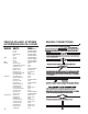
Programming instructions

11
(Parking Light Output continued)
If the circuit is (+) positive and pulls less than 10 amps, connect the BROWN wire from
the 9-pin harness directly to the vehicles parking light wire. If the circuit is negative,
you must use a relay if not hooking to the BCM or the vehicles computer. Part #775
is required for most negative parking light circuits.
Connect the BROWN wire from the 9-pin harness to the vehicles parking light circuit
if you are not using a relay.
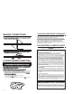
BRAKE INPUTBRAKE INPUT (BLUE WITH BLACK STRIPE) (BLUE WITH BLACK STRIPE)
The brake wire is located on the switch near and above the brake pedal, if you cannot
locate this wire at the brake switch, you will then need to locate a wire at the rear window
brake light or at the brake light system in the rear of the vehicle. The correct wire will
show +12V only when the brake is pressed. Connect the BLUE WITH BLACK STRIPEBLUE WITH BLACK STRIPE
from the 9-pin harness to this wire.
ANTENNAANTENNA (YELLOW) (YELLOW)
For best results, run the antenna (YELLOW WITH BLACK YELLOW WITH BLACK TIPTIP in the 9-pin harness)
as straight as possible. Do not place the antenna next to any metDo not place the antenna next to any metal pal partarts or the vehicles or the vehicless
main computer control.main computer control.
FFACTACTORORYY ALARM SHUTALARM SHUT DOWN WIRE (F DOWN WIRE (FASD) (-) (RED WITH BLACK STRIPE)ASD) (-) (RED WITH BLACK STRIPE)
If your vehicle is equipped with a factory alarm system (as most vehicles with
a factory keyless entry are) or, if your vehicle DOES NOT have a factory remote
control that honks the horn when locking and unlocking the doors, or when
you use the key in the drivers door, you DO NOT get a light on the dash that
says security then mostly you will not need to use this wire. If your vehicle
is so equipped, probe for a small gauge wire (usually found in the drivers side
kick panel) that shows (-) ground when the door lock cylinder is turned to the
unlock position using the key. This wire will usually show a (+) positive voltage
before turning the key. NOTENOTE: Some factory disarm wires remain neutral before
you turn the key to unlock instead of +12v positive. Connect the RED WITHRED WITH
BLACK STRIPEBLACK STRIPE wire from the 9-pin harness to this wire.
HOOD PIN SWITCH (BLACK WITH BLUE STRIPE)HOOD PIN SWITCH (BLACK WITH BLUE STRIPE)
This feature will keep the engine from starting, or shut off the engine when in
remote start mode only. The hood pin switch has no control over the engine
when started with the ignition key or under normal operation. Locate a good
chassis ground, if at all possible do not install the pin switch in the rain gutter.
Drill a 5/16 hole, insert the pin switch into the hole and tighten. Check for the
hood adjustment, there is approximately 1/4 adjustment in the pin switch.
Close the hood easy, making sure that the pin switch is not keeping the hood
from closing all the way, if it does, cut off approximately 1/8 of the black plastic
off of the top of the hoodpin switch and try closing the hood again. Check to
make sure that the hoodpin switch remains neutral when the hood is closed
and shows ground when the hood is open. Plug the BLACK WITH BLUEBLACK WITH BLUE
STRIPESTRIPE wire from the 9-pin harness into the bottom of the hood pin switch.
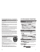
TTACH INPUTACH INPUT (BLACK WITH WHITE STRIPE) (BLACK WITH WHITE STRIPE) (Optional)
By this time, you should have determined the way you want your vehicle to
start (tach or tachless). Tachless uses voltage electronic signals and timing to
work. Tach types use a signal directly from the ignition coil. If you have chosen
the TACHLESS start option, simply proceed to the next step and skip the
following instructions. Make sure you tape this wire up if not used. For TACH
mode connect the BLACK WITH WHITE STRIPEBLACK WITH WHITE STRIPE wire from the 9-pin harness
to the negative side of the coil or the tach wire at the coil pack under the hood.
To find the coil pack follow the spark plug wires back to their beginning point.
To operate in tach mode, make sure to program tach option. See programming
tach option page 15.
AUXILIARAUXILIARYY INPUT INPUT (BLUE) (For (BLUE) (For AfAftermarket termarket Alarms)Alarms)
If you use this starter with an aftermarket alarm, connect the BLUEBLUE wire from
the 9-pin harness to the second or third channel output of your existing alarm.
When the output is activated, a signal will activate the remote starter. NOTE:
This wire will also be used if you wish to connect the unit up to operate
off of your Factory Keyless Entry. See Programming to Start Your Vehicle
from your Factory Keyless Entry, page 15. (Extra part #775 relay is required.
See diagram, page 12.)
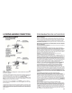
LOCATING & MAKING CONNECTIONS
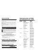
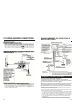
CONTACT MÉCANIQUE DE SÉCURITÉ DE POINT MORT
Quand vous installez une télécommande de démarrage Bulldog dans un
véhicule GM ou un Dodge Dakota fabriqué avant 1996, vous devez :
Utilisez le schéma ci-dessous pour créer un circuit qui empêche la
télécommande de démarrage de mettre le moteur en marche, sauf si la
clé est retirée du commutateur dallumage.
GM À PROPULSION ARRIÈRE, AVANT 1996,
AVEC FIL VIOLET DE LANCEMENT
Relais n
o
775 en option requis
CONTACT DE
SÉCURITÉ DE POINT MORT
Masse
Masse
86
30
87a
87
85
Fusible
5 A
À relier au gros
fil blanc du
faisceau à
quatre relais
Fil de contact de
capot négatif (-)
Afficheur multi-
message ou
tonalité de clé
Contact de porte contucteur
Barillet de clé
HANANEHANANE
VERVERTT
NOIRNOIR
JAUNEJAUNE
BLEUBLEU
BLANCBLANC
NE PNE PAS UTILISER LE FILAS UTILISER LE FIL ROUGE; L ROUGE; LISOLERISOLER
ROUGEROUGE
FUSIBLE
DODGE DAKOTA AVANT 1996
Relais n
o
775 en option requis
Masse
NOIR/NOIR/
BLEU CLAIRBLEU CLAIR
Masse
86
30
87a
87
85
CLAIRCLAIR
BLEU/VERBLEU/VERTT
NOIRNOIR
JAUNEJAUNE
BLEUBLEU
BLANCBLANC
ROUGEROUGE
Fusible
5 A
À relier au gros
fil blanc du
faisceau à
quatre relais
Fil de contact de
capot négatif (-)
NE PNE PAS UTILISER LE FILAS UTILISER LE FIL ROUGE; L ROUGE; LISOLERISOLER
FUSIBLE
Afficheur multi-
message ou
tonalité de clé
Contact de porte contucteur
Barillet de clé
34