
Programming instructions

15
OPERATOR PROGRAMMING
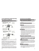
ADDING ADDING ADDITIONALADDITIONAL REMOTES USING REMOTES USING AA WORKING REMOTE WORKING REMOTE
Press and hold the brake, press and hold Button #1 on the working remote
for approx. 5 seconds or until the parking lights flash (1) one time, release
button #1 on this remote and press and any button on the NEW remote,
the parking lights will flash (3) three times, the new remote is now
programmed.
ADDING ADDING ADDITIONALADDITIONAL REMOTES WITHOUT REMOTES WITHOUT AA WORKING REMOTE WORKING REMOTE
You must first follow the procedure for clearing the memory on page 16
then proceed with the initialization procedure on page 13.
TTach/Tach/Tachless Optionachless Option
Press and Hold the BRAKE, with the brake held, press and hold button
#2 until the parking lights flash (2) two times, release button #2 and press
and release button #1 the parking lights will flash (1) once. The unit is
now programmed for TACH mode. If you press and release button #1
again and the parking lights flash (2) two times, the unit is programmed
for TACHLESS mode, release the brake and the parking lights will flash
(3) three times.
Note: The factory default setting is TACHLESS mode.
Programming TProgramming Tach Learnach Learn
Press and hold the brake, with the brake held, press and hold button #2
until the parking lights flash (2) two times, release button #2, then press
and release buttons #1 and #2 at the same time and the parking lights
will flash (2) two times, while still holding the brake, start the vehicle with
the ignition key. With the vehicle running, press Buttons #1 and #2, the
parking lights will flash (1) one time signifying the tach learn mode is
entered. Release Buttons #1 and #2 and in approximately 5 seconds the
parking lights will flash (3) three times, the tach signal is now learned.
Turn off the ignition key and release the brake.
Note**** The unit must be programmed for TACH mode before the
TACH LEARN function will program.
Programming to SProgramming to Sttart your Vart your Vehicle with your Factory Keyless Entryehicle with your Factory Keyless Entry
Press and hold the brake, then press and hold Button #2 on the Bulldog remote
transmitter until the parking lights flash once (if hooked up) or for approximately
six seconds or until the unit clicks or flashes one time. Then press Button #2 again,
the parking lights will flash (1) time. If they flash twice, press Button #2 again until
the parking lights flash once. The unit is now in the factory keyless mode. NOTE:NOTE:
AA relay is required for this feature if the lock wire on the vehi relay is required for this feature if the lock wire on the vehicle is a (+) positivecle is a (+) positive
output.output.
Programming for Programming for AfAftermarket termarket Alarm SAlarm Sttartingarting
Press and hold the brake, press and hold Button #2 on the Bulldog remote
transmitter until the parking lights flash one time (if hooked up) or for approximately
six seconds until the unit clicks or flashes one time. Then press Button #2 again,
the parking lights will flash (1) time. If they flash twice, press Button #2 again until
the parking lights flash once. The unit is now in the factory keyless mode. NOTE:
A relay is required for this feature if the lock wire on the vehicle is a (+)
positive output.
Auxiliary InputAuxiliary Input
(For your factory keyless or af(For your factory keyless or aftermarket alarm)termarket alarm)
When connecting this unit to a factory keyless entry system, you must locate the
door lock wire that tests as a positive when you press the lock button on the factory
remote. A relay Part #775 will be needed to convert the positive output from the
door lock to a negative pulse for the BLUE wire on the 9-pin harness. If the wire
is negative when you press the lock button on the factory remote, you can tie
directly into the BLUEBLUE wire. This wire is usually located in the drivers kick panel,
in the harness that is coming from the drivers door.
LOCALISATION ET RÉALISATION
DES BRANCHEMENTS
MISE EN GARDE : Vérifiez la position du commutateur avant de brancher les
fils. Vous pouvez endommager le module de commande si le commutateur nest
pas à la bonne position.
Le commutateur se trouve entre le faisceau à neuf broches et la borne n
o
1 dallumage.
Le commutateur vers lintérieur du module de commande est réglé à la position
positive (+) et, vers lextérieur du module, à la position négative (-).
Sondez le fil de feux de stationnement du véhicule. Si la sonde indique une
tension positive (+) ou si le voyant ROUGE sallume uniquement quand les feux de
stationnement sont allumés à la position « ON », le circuit est positif (+). (Mettez
le commutateur à la position rentrée.)
Si la sonde de mesure indique une tension négative (-) ou si le voyant VERT sallume
uniquement quand les feux de stationnement sont allumés à la position « ON », le
circuit est négatif (-). (Mettez le commutateur à la position sortie).
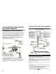
La sortie feux de stationnement du module de commande est prévue pour 10 A
maximum et convient à la plupart des véhicules. Si vous ajoutez dautres éclairages
et dispositifs au circuit des feux de stationnement du véhicule, vérifiez lintensité de
courant à laide dun multimètre. Un relais (pièce n
o
775) est nécessaire si les feux
de stationnement du véhicule consomment plus de 10 A. Voir le schéma ci-dessus.
SORTIE FEUX DE STATIONNEMENT (+/-) (BRUN) (La pièce 775 en option
peut être nécessaire)
30