INSTALLATION GUIDE OWNER'S GUIDE Keyless Entry and Alarm System Model 1402 Thank you for purchasing an American made product by Bulldog Security. To order additional transmitters or other accessories, visit our website at www.directwholesale.net or call 1-800-659-0764 FOR TECHNICAL ASSISTANCE, CALL 1-800-878-8007 www.bulldogsecurity.com email: techsupp@bulldogsecurity.com Wiring diagrams for your vehicle can be accessed by visiting www.bulldogsecurity.
CONTENTS SYSTEM FEATURES System Features ...............................................4-5 2 Four-Button Control your car from an extended Extended Range distance. Remote Control System Components.............................................6 Keyless Entry Remotely locks and unlocks your power door locks. Remote Locking and Unlocking with Ignition Switch Remotely locks your power door locks when the ignition is turned on and unlocks your power door locks when the ignition is turned off.
SYSTEM FEATURES SYSTEM COMPONENTS CONT. On-Board Parking Light Relay Built-in relay provides a positive (+) parking light output. No relay needed. On-Board Door Lock Relay Built-in relay for Type A, Type B and Type C door locks. Plug In Six A visual theft deterrent that flashes when Function LED the system is armed. Lets you know Status Indicator which zone has been violated, and and provides a visual reference for you.
BEFORE YOU BEGIN PRECAUTIONS CONT. technology and components. It is computer controlled and manufactured in the U.S.A. The dependability and variety of features make Bulldog Security the leader in the industry. Enjoy your new system for years to come! Since there are many different makes and models of vehicles, look at the wiring chart on our website, www.bulldogsecurity.com/wires.htm. CONT. DO NOT plug the harnesses into the control module until all connections have been made.
MAKING CONNECTIONS MAKING CONNECTIONS CONT. 5. Wrap the wire around one side then the other and finally around itself as shown. 1 2 CONT. 3. Lay upper twisted pair of wires over right wire as shown. Bring lower twisted pair of wires up to meet the left wire as shown. 3 6. Use electrical tape to wrap. Be sure to cover the wire about two inches on either side of the connection. First pull the wire that you have just connected along side the wire you connected to, tape and wire tie them together.
LOCATING & MAKING CONNECTIONS CONT. LOCATING & MAKING CONNECTIONS CONT. 3. Turn the ignition ON. Probe for a wire that shows 12 volts only when the ignition is on. Confirm this by turning the ignition on and off while probing each wire. Optional Part #775 CONNECTING THE NEGATIVE TO FACTORY TRUNK OUTPUT #1, BUTTON #2 WIRE OR OTHER THE BLUE wire is used to operate a POSITIVE remote car starter, window roll-up ACTIVATED ACCESSORY module, etc. for as long as 87a transmitter Button #2 is depressed.
LOCATING & MAKING CONNECTIONS CONT. LOCATING & MAKING CONNECTIONS CONT. CONNECTING THE MAIN WIRING HARNESS TO THE MODULE Carefully plug the main harness into the 1402 module. DO NOT plug the harnesses into the control module until all connections have been made. Be careful to line up the pins on the unit with the wiring harness plug (lip up - Red wire to the right). Failure to do this will cause severe damage to the unit and possibly to the vehicle.
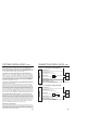
LOCATING & MAKING CONNECTIONS CONT. LOCATING & MAKING CONNECTIONS CONT. CONNECTING THE CAR HORN WIRE You must use optional part #775. Using the siren base as a template, mark the three mounting holes. Drill a 1/8 inch hole at each mounting hole location, taking care not to damage anything behind the mounting surface. YELLOW To (-) horn wire in vehicle Back of #775 (relay and harness) To (+) horn honk output wire from unit BLACK/BLUE 86 87a 85 Connect the wires as shown.
LOCATING & MAKING CONNECTIONS CONT. LOCATING & MAKING CONNECTIONS CONT. Drill a 5/16 inch hole in the mounting surface, taking care not to damage anything behind the surface. sensor to 22 gauge BLACK wire with green tag. If you add more than one sensor, a diode must also be added. NOTE: This unit is designed to use only a single stage sensor. If you are using a dual stage sensor, use only the major output of the sensor.
wires tests (+) positive when lock is pressed and the other tests (+) positive when they are unlocked, your vehicle has a Type A door locking system. Make sure to mark which wire is lock and unlock. Proceed to Connecting Door Locks, Connecting Door Locks. NOTE: Type A and Type C locks will test the same, until you test for ground. Make sure you run both tests before making your connections.
CONNECTING DOOR LOCKS CONT. Type C Reverse Polarity (5-pin harness) POWER DOOR LOCK MOTOR BLUE/BLACK Lock MODULE BLUE/WHITE Lock BUTTON #1 ARM/DISARM BUTTON #3 OPTION #3 RED/BLACK FUSE GREEN/BLACK Unlock GREEN/WHITE Unlock UNLOCK NOTE: You will need to cut factory wiring to make an end to end connection, see Making Connections on pages 2-4.
HOW TO USE YOUR REMOTE TRANSMITTER HOW TO USE YOUR REMOTE TRANSMITTER CONT. PASSIVE ARMING To activate Passive Arming, disarm the system, then hold Button #3 for ten (10) seconds. The system will chirp once. Press Button #3 again within two (2) seconds. The system will chirp once to indicate that passive arming is now programmed. To deactivate passive arming, hold Button #3 for ten seconds until one chirp occurs.
HOW TO USE YOUR REMOTE TRANSMITTER CONT. DUAL LOCK/UNLOCK PULSE To program the Dual Lock/Unlock Pulse, press Button #3 for ten (10) seconds. The system will chirp once. Press Button #4 within two (2) seconds and the system will chirp once again to signify that the dual unlock pulse is programmed. The above steps must be repeated to program dual pulse lock (2 chirps), both dual pulse lock and unlock (3 chirps), then no dual pulse functions (4 chirps).
YOUR WARRANTY Here's how your warranty works: JBS Technologies warrants to the original customer, and the original car a limited lifetime warranty. Within 12 months of purchase, JBS Technologies will repair or replace, our option, any defective system at no charge. After 12 months from date of purchase JBS Technologies will, at our option, repair or replace the system for a $10 shipping and handling fee.