
Data Sheet
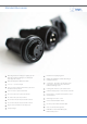
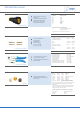
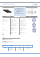

Buccaneer for Power 26
BUCCANEER FOR POWER
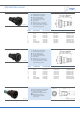
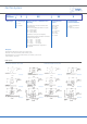
Part No System
PX0xxx
X XX
XX X
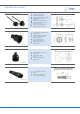
Body Styles
Contacts Type
P = Pin
S = Socket
Cable Acceptance or PCB/Rear Panel
Mounting
Flex Cable and In-line Flex Connectors cable
acceptance use:
Blank = 6-8mm (Black) standard for 2-12 pole
04 = 3.5-5mm (Grey)
05 = 5-7mm (White)
07 = 7-9mm (Yellow)
(standard for 25 way, no sux required)
PCB (PX0707) and Rear Panel Mount connectors
(PX0708 and PX0709) use:
Front Panel, Bulkhead and Flange Mount -
not required:
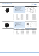
Insert/Gland Nut
Colour
Insert/Gland Nut
Colour Combination
1 = Insert and Gland Nut
Coloured
2 = Insert only Coloured
02 = 2 pole
04 = 4 pole
07 = 7 pole
12 = 12 pole
03 = 3 pole
06 = 6 pole
09 = 9 pole
25 = 25 pole
Blank = Black
BL = Blue
GN = Green
GY = Grey
LG = Light Grey
RD = Red
WH = White
YL = Yellow
Examples:
PX0707/P/06= PCB Panel connector, pin contacts, 6 pole
PX0731/S = Flex Cable connector, socket contacts, 3 pole
PX0732/P/07/BL2 = In-Line Flex Cable connector, pin contacts, 3 pole, 7-9mm
cable acceptance, blue insert
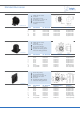
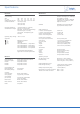
PCB Layouts
Sockets
Contact Nos viewed from rear of panel
Pins
Contact Nos viewed from rear panel
PX0707/S/03 PX0707/S/04
PX0707/S/06 PX0707/S/09
PX0707/S/12 PX0707/S/25
PX0707/P/03 PX0707/P/04
PX0707/P/06 PX0707/P/09
PX0707/P/12 PX0707/P/25