
Instruction Manual
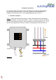
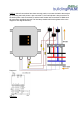

STEP 4 ; The 3-Phase IoT Energy Meter will have two sets of wires - a set of four connection wires (a
black connection wire, a red connection wire, a blue connection wire and a white connection wire),
and a set of CT wires. The CT wires are paired in groups of two - there are three such groups in total.
Each group is labelled as either “1”, “2” or “3”.
Connect each connection wire to the terminal in the following manner :
a. The black connection wire should be connected to the phase 1 wire terminal (T1), where the
load’s phase 1 wire connects.
b. The red connection wire should be connected to the phase 2 wire terminal (T2), where the
load’s phase 2 wire connects.
c. The blue connection wire should be connected to the phase 3 wire terminal (T3), where the
load’s phase 3 wire connects.
d. The white connection wire should be connected to the neutral wire terminal (T4), where the
load’s neutral wire connects.
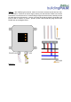
Connect each CT wire group, using the connectors provided, to the CTs in the phase wires, as follows
:
a. The CT containing the phase 1 wire must be connected to the CT wire group labelled “1”.
b. The CT containing the phase 2 wire must be connected to the CT wire group labelled “2”.
c. The CT containing the phase 3 wire must be connected to the CT wire group labelled “3”.
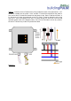
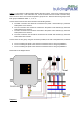
Please refer to the diagram below.
Diagram 4