
Full Product Manual


37
HEAT.WAV WATER HEATER CONNECTIONS
All Y Series systems come with a high performance heat.wav
heater. With no pressure switch, it features in.flo integrated
dry-fire protection.
The heat.wav heater is factory configured for 240 V / 4 kW,
but it can be converted to a dedicated 120 V / 1 kW by simply
adding a cable connection. (120 V conversion is available on
North American in.ye-3 models only).
The heat.wav heater is also offered in 240 V / 5,5 kW or 240 V
/ 2 kW versions.
heat.wav specification summary:
• Supports 120 V or 240 V
• Incoloy® heater element
• Protected by external breaker (not fused)*
* Note: European models are 230-240 V only and are fuse
protected.
Part numbers:
9917-101959 (cable for conversion)
9920-101449 (5.5 kW heat.wav heater)
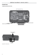
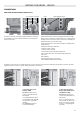
Connections for 120 V
heaters (1 kW)
BROWN wire must be cor-
rectly connected between
P12 and P10.
For early North American ver-
sion installations the YELLOW
wire must be between P25
and P20.
The ORANGE wire must be
between P24 and P16.
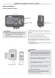
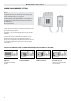
Connections for 240 V
heaters (North American
installations only).
BROWN wire must be cor-
rectly connected between
P12 and P9.
Note: To convert model to a
120 V system, the white (com-
mon) accessory wire must be
moved. See wiring diagram
for details.
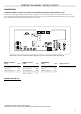
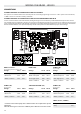
CONNECTIONS
WIRING DIAGRAM W3000
All heater connections are accessible when the cover is removed. Connections include the in.flo dry-fire protection, hi-limit/
regulation probe connectors, power and ground cable connections.
Live Return Ground in.flo flo Regulation probe