
Full Product Manual
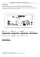
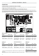


WIRING DIAGRAM W2000, W2001
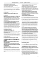
ELECTRICAL WIRING: ALL MODELS
ELECTRICAL WIRING
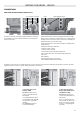
Bonding lugs
Main power entry
Main electrical box GFCI panel
Main power entry
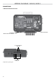
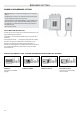
To complete the electrical connections of the in.yj control
system you will need a Phillips screwdriver and a flat-head
screwdriver.
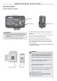
Remove the screws from the system control lid and remove it.
Remove 5 1/2" (142 mm) of cable insulation.
Strip away 1/2" (15 mm) of insulation from each wire.
Pull the cable through the cutout of the box and secure it
with a 3/4" NPT strain relief* (hole diameter 1.09" {27.6 mm}).
Ensure that the NPT strain relief clamps around the outer
sheath of the cable.
* For CE/AUS/NZ use an IEC certified plastic bushing that will
maintain the IPX5 rating.
WARNING!
Disconnect power before starting electrical work.
Wiring must be completed by a qualified electrician
and must be done in accordance with the local
electrical code.
Do not use a wire gauge bigger than 8 AWG.
WARNING!
For units for use in other than single-family dwellings, a
clearly labeled emergency switch shall be provided as
part of the installation. The switch shall be readily acces-
sible to the occupants and shall be installed at least 5'
(1.52 m) away, adjacent to, and within sight of the unit.
-----
This product must always be connected to a circuit
protected by a ground fault interrupter.
-----
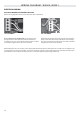
Proper wiring of the electrical service box, GFCI and
in.yj terminal block is essential!
-----
Check your electrical code for local regulations. Only
copper wire should be used, never aluminum.
-----
Disposal of the product
The appliance (or the product) must be disposed
of separately in accordance with the local waste
disposal legislation in force.
33