
Installation Instructions


SSB 6720818454 (2016/02) US
Applications | 53
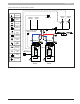
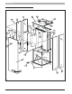
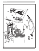
(*) NOTICE: The maximum amp load for each pump is 1 A
when 2 or 3 pumps are connected. For this reason, if the
power consumption of each pump is higher than 84 watt,
use a relay as shown in gure.
If just one pump is connected, the maximum amp load
of this single pump is 2 A. For this reason if the power
consumption of the pump is higher than 168 watt, use a
relay as shown in Fig. 81.
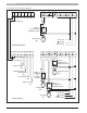
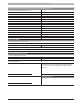
► The low voltage connections for “Primary boiler” are:
Terminal Number. Device
1-2 Cascade link
7-8 Outdoor air sensor (optional)
9-10 DHW tank sensor or Tank Thermostat (Aquastat)
11-12 Room thermostat
13-14 Supply sensor
► The low voltage connections for “Secondary boiler” are:
Terminal Number. Device
1-2 Cascade link
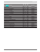
► The high voltage connections for “Primary boiler” are:
Terminal Number. Device
101-102-103 Boiler pump
104-105-106 CH pump
107-108-109 DHW tank pump
► The high voltage connections for “Secondary boiler” are:
Terminal Number. Device
101-102-103 Boiler pump
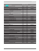
8.3.1 Settings
Set the parameters as indicated in the following table (for the parameter
list see section “5.5 Parameters list”):
No. Description Value Comment
1
Central Heating
Mode
0 Outdoor air sensor not present
1
Outdoor air sensor present. Reset
curve activate
2 Mod Pump Mode 2 Enabled CH pump and DHW pump
35 DHW mode
0 No indirect sanitary water installed
1 Indirect sanitary water with sensor
2
Indirect sanitary water with tank
thermostat
If CH mode is set to 1 and an outdoor air sensor is present, set the reset
curve parameter as follows (to set these values see also section “5.6
Outdoor reset”):
No. Description Value (°F)
19 Design Supply Temp 180
20 Design Outdoor Temp 25
21 Baseline Supply Temp 104
22 Baseline Outdoor Temp 70
23 Design Supply Min Limit 40
24 Design Supply Max Limit 180
25 Warm Weather Shutdn 68