
Installation Instructions


6720818454 (2016/02) US SSB
46 | Applications
8 Applications
The following shows possible system diagrams.
NOTICE: Application drawings in this manual are
conceptual only and do not purport to address all design,
installation, code, or safety considerations. The diagrams
in this manual are for reference only for code ofcials,
designers and licensed installers. It is expected that
installers have adequate knowledge of national and
local codes, as well as accepted industry practices, and
are trained on equipment, procedures, and applications
involved. Drawings are not to scale. Refer to the boiler,
control and module installation manuals for additional
detailed information.
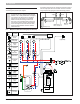
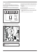
8.1 Multiple zone with indirect tank (pump for each zone)
Fig. 73
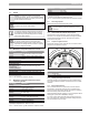
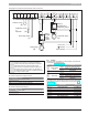
The following system diagrams are showing primary/secondary piping. As
alternative a appropriate sized low loss header can also be used. When
using primary/secondary piping please follow the following guidelines:
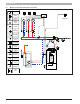
Fig. 74
T TT T
...
Zone relay
X X
T
T
DHW Sensor
or Aquastat
Expansion
Tank
Auto-Fill
Air
Eliminator
Shut-off
valve
Condensate
drain
Outdoor air
sensor
Room
Thermostat
Flow Check
Supply
sensor
Heating
zone
Domestic
Hot Water
Circulator
Purge Drain
Relief valve
and
pressure
gauge
Back-flow
preventer
(optional)
1
2
3
4
5
Primary Loop
Secondary
Supply
Secondary
Return
“D” “D”
Minimum 8 X “D”
Minimum
4 X “D”
Maximum 4 X “D”
Not to exceed 12”