
Installation Instructions


6720818454 (2016/02) US SSB
52 | Applications
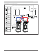
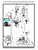
For this installation the wiring is shown in gure below:
Fig. 81
123
45
6
7
89
10 11 12 13 14
101102 103104 105 106107 108109
11
61
18117
L
N
L
N
L
N
CASCADE
LINK
MOD
BUS
Gas
Switch
Out
Door
DHW Tank
Sensor
Room
Thermostat
Supply
Sensor
Boiler
Pump
Pump DHW
120 V Main in
N
L
Boiler pump
DHW tank pump
Room thermostat
DHW tank sensor
or Aquastat
Outdoor sensor
110111 112
L
N
Alarm
113114 115
L
N
120 V Aux
L
N
Pump CH
N
L
3 Way
(3)
(2)
(5)
(8)
(6)
12345678910 11 12 13 14
CASCADE
LINK
MOD
BUS
Gas
Switch
Out
Door
DHW Tank
Sensor
Room
Thermostat
Supply
Sensor
N
L
120 V Neutral
Ground
120 V Line
120 V Neutral
Ground
120 V Line
Boiler pump
(9)
Supply sensor
CH pump
N
L
(1)
(7)
Primary boiler
Secondary boiler
(4)
Cascade link
(4)
Cascade link
GND
GND
GND
GND
GNDGND
GNDGND GND
GND
101102 103104 105 106 107 108109
11
61
18117
L
N
L
N
L
N
Boiler
Pump
Pump DHW
120 V Main in
110111 112
L
N
Alarm
113114 115
L
N
120 V Aux
L
N
Pump CH
3 Way
GND
GNDGND
GNDGND GND
Relay (*)
Furnished and
Installed by others
Relay (*)
Furnished and
Installed by others
Relay (*)
Furnished
and
Installed
by others
Relay (*)
Furnished and
Installed by others