
Installation Instructions
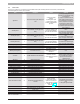


6720818454 (2016/02) US SSB
50 | Applications
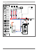
8.3 Cascade connection
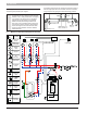
The SSB boilers can be connected together to form a cascade with a
maximum of 16 boilers. In this case, one boiler will be the manager of the
other boilers connected. This boiler is named “Primary”. The other one(s)
are named “Secondary”.
To have a cascade it is necessary to connect together the boilers using
the “Cascade link” (pin 1-2) in parallel as shown in the following gure:
Fig. 78
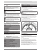
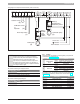
To dene the “Primary” boiler of the cascade set to “ON” the “S4 switch”.
This switch has to be set “OFF” in all the “Secondary” boilers (see the
following gure).
Fig. 79
CAUTION: Change the position of the S4 switch only when
the boiler is off.
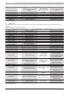
Each cascade boiler has to be identied by an address (parameter N° 73
“Boiler Address” )different from the others. To dene these address follow
the steps below:
► Switch on the “Primary boiler” and set the parameter N°73 (“Boiler
Address”) to 1
► Switch off the “Primary boiler”
► Switch on the second boiler and set the parameter N°73 to 2.
► Switch off the second boiler
► Continue with steps 3 and 4 for each boiler (each “Secondary” boiler
has to be a different number from 2 to 16 and the “Primary” must be
number 1)
► Switch on all boilers starting with the “Primary boiler”
123
CASCADE
LINK
123
CASCADE
LINK
Boiler 1
Boiler 2
Boiler 16
...
123456789
10 11 12 13 14
CASCADE
LINK
MOD
BUS
Gas
Switch
Out
Door
DHW Tank
Sensor
Room
Thermostat
Supply
Sensor
ON
OFF
S4