
Installation Instructions

SSB 6720818454 (2016/02) US
Installation | 25
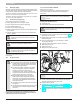
4.7.2 Connecting ue gas systems
Optional vent systems are:
• Twin pipe, concentric pipe and 1 pipe using room air
• Approved materials PVC, CPVC, Stainless Steel, PP and PP-Flex
(M&G Duravent PolyPro and Centrotherm InnoFlue)
• Sealed combustion or room air intake
• Terminations can be either horizontal or vertical
• The diameters of the ue outlet and combustion air intake inlet are
designed to t standard PP, PVC, CPVC and stainless steel pipes.
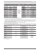
The following table gives the diameter of the ue adapter on the
boiler.
Boiler SSB255 SSB399 SSB512
Diameters 3” - 80mm 4” - 100mm 4” - 100mm
Tab. 3
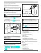
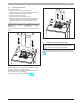
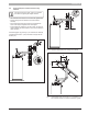
Insert the exhaust pipe and the air intake pipe as shown in the following
gure:
Fig. 26
Insert the ue exhaust pipe “A” completely into the adapter and tighten
the clamp “B” present in the ue exhaust adapter.
Insert the air intake pipe “C” completely into the adapter and tighten the
clamp “D” present in the air intake adapter.
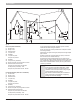
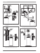
The correct ow direction into two pipes is shown in Fig. 27.
Fig. 27
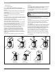
4.7.3 Installation of the exhaust and air intake system
NOTICE: Do not extend exposed vent pipe outside the
building beyond recommended distance of 39” or 1 meter.
Condensate could freeze and block vent pipe
Vent should terminate at least 3 feet (915 mm) away from adjacent walls,
inside corners and 5 feet (1525 mm) below roof overhang ( [X2], [X4], see
Fig. 28)
C
A
B
D