
Installation Instructions

10
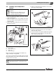
Mounting the burner
Logano G615 - Subject to technical modifications
42
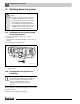
10 Mounting the burner
This chapter explains how to install the burner.
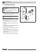
B Close the burner door and secure with 4 machine
screws (M16 × 140) in the positions shown. Tighten
the machine screws evenly crosswise.
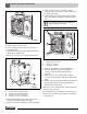
If you have ordered an undrilled burner plate, you will have
to machine this on site:
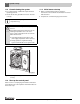
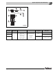
B Drill or cut the burner plate (Æ Fig. 56, [1]) to match
the required burner tube diameter Ø 10 5/8 inches
(270 mm).
B Drill burner attachment holes using the burner flange as
a template.
B Screw burner plate onto the burner door (seal with GP
sealant rope; diameter Ø 25/64 inches (10 mm)).
B Screw the burner to the burner plate.
B Cut insulating rings to match the burner tube diameter
(Æ Fig. 56, [2]).
B Fill the remaining gap between the burner door thermal
insulation and the burner tube Æ Fig. 56, [4]) using the
appropriate insulating rings or boiler packing insulation
(Æ Fig. 56, [3]).
B Connect the vent blower connection to the burner to
ensure the inspection window remains free of deposits.
Fig. 56 Mounting the burner
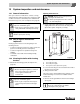
NOTICE: Damage to boiler due to incorrect
burner.
B Only use burners that conform to the
technical requirements of the boiler (see
Æ Chapter 3, page 11).
You can obtain undrilled or predrilled burner
plates (hole pattern depends on burner) as
accessories from Buderus.
6 720 642 623-63.1o
2
3
4
1
(145 mm)
5 45/64"