
Installation Instructions

9
Installing the control panel
Logano G615 - Subject to technical modifications
39
9 Installing the control panel
This section explains how to install a Logamatic 4000
series control panel and its set of temperature sensors.
9.1 Installing the control panel
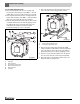
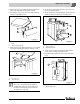
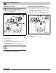
Fig. 50 shows the control panel and front top cover “A”
from behind.
B Loosen both screws on top of the control panel and
remove the cover. Lift off the terminal cover toward the
top.
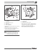
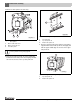
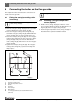
Mounting the control panel
B Fit the control panel at the front by inserting the
alignment tabs into the oval holes in the front top boiler
cover.
B Tilt the control panel forward and then tip back.
The flexible hooks must engage with the rectangular
openings at the rear of the front boiler cover.
B Attach the base of the control panel to the top cover
using two self-tapping screws.
Fig. 50 Installing the control panel
1 Terminal cover
2 Flexible hooks
3 Rectangular cutouts in the front top boiler cover
4 Alignment tabs
5 Oval holes in the front top boiler cover
6 Cable duct
7 Front top boiler cover
DANGER: Risk to life from electric shock.
B Electrical work may only be performed by
professionals with appropriate
qualifications.
B Before opening the appliance,
isolate all poles of the mains power supply
and secure against unintentional
reconnection.
B Please observe all installation instructions.
1
2
45637
6 720 615 362-18.2O