
Installation Instructions
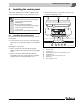

8
Connecting the boiler on the flue gas side
Logano G615 - Subject to technical modifications
38
8 Connecting the boiler on the flue gas side
This chapter describes how the boiler connections are
made on the flue gas side.
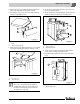
8.1 Fitting the vent pipe sealing collar
(accessory)
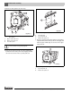
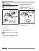
B Push the vent pipe (Æ Fig. 49, [4]) as far as possible
onto the draft diverter outlet (Æ Fig. 49, [6]).
B Place the vent pipe sealing collar (Æ Fig. 49, [1])
around the vent pipe (Æ Fig. 49, [4]) and draft diverter
(Æ Fig. 49, [6]) outlet so that it overlaps at the top.
B Place hose clamps (Æ Fig. 49, [5]) over the vent pipe
sealing collar (Æ Fig 49, [1]). One of the hose clamps
(Æ Fig. 49, [5]) must press onto the draft diverter
outlet (Æ Fig. 49, [6]) and and one onto the vent pipe
(Æ Fig. 49, [4]).
B Tighten hose clamps (Æ Fig. 49, [5]). The vent pipe
sealing collar (Æ Fig. 49, [1] must fit smoothly and
firmly in place.
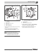
Fig. 49 Sealing the vent pipe
1 Vent pipe sealing collar
2 Flue gas temperature sensor
3 Sleeve
4 Vent pipe
5 Hose clamps
6 Draft diverter
A 2 × Vent pipe diameter, at least 28 22/64 inches
(720 mm)
8.2 Installing a flue gas temperature
sensor (option)
B Weld a sleeve (Æ Fig. 49, [3]) at a distance of two
(2) × vent pipe diameters (A) from the draft diverter (Æ
Fig. 49, [6]) in the vent pipe (Æ Fig. 49, [4]).
B Fit the flue gas temperature sensor (Æ Fig. 49, [2]) as
described in the separate installation manual.
We recommend you use a vent pipe sealing
collar (Æ Fig. 49, [1]).
Retighten the hose clamps if needed.