
Installation Instructions


7
Boiler block assembly
Logano G615 - Subject to technical modifications
24
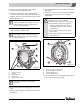
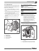
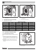
7.4 Inserting the supply pipe (parts
crate)
For boilers with 9 – 11 sections, the supply pipe consists
of 2 pieces, and 12 – 16 sections 3 pieces.
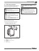
B Push the flat gasket over the supply pipe.
B Push the supply pipe from the front into the top boiler
hub.
B Close off with flange cover.
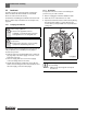
Fig. 22 Sealing in the supply pipe
1 Flat gasket
2 Flange cover
3 Cam
4 Supply pipe
5 Notch in top boiler hub
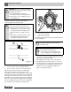
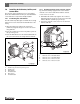
7.5 Installing sensor well (fittings crate)
Sensor well R ¾ "
B Seal and install sensor well R ¾ " from the front
(length: 4 21/64" (110 mm)) into the top R ¾ " tapped
hole of the supply connection.
Sensor well R ½ "
B Seal and install sensor well R ½ " from the front
(length: 4 21/64" (110 mm)) into the lower R ½ "
tapped hole of the supply connection.
Fig. 23 Installing sensor wells
1 Sensor well R ¾ "
2 Sensor well R ½ "
The supply pipe must be fixed in such a way
that the holes on the supply pipe are
positioned at the correct angle. This ensures
optimum distribution of water in the area of
the top boiler hub (Thermostream principle).
B Make sure that the cam [3]) on the end
plate of the supply pipe (Æ Fig. 22, [3]) fits
in the notch in the top boiler hub
(Æ Fig 22, [5]).