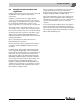
Installation and Service Instructions Low-temperature oil/ gas boiler WARNING: If installation, adjustment, modification, operation or maintenance of the heating system is carried out by an unqualified person, this may result in personal injury or property damage. The directions of this installation manual must be followed precisely. If support or additional information is required, contact a qualified service company, service provider or the gas company.
Table of Contents About this manual The appliance has been tested to meet all national requirements in effect on the date of manufacture. The certificates are on file with the manufacturer. This installation and maintenance instructions contain important information for the safe and proper installation, initial start-up and maintenance of the oil/gas-fired boiler Logano G615. Table of Contents 1 Guideline to symbols and safety instructions 4 1.1 Guideline to symbols . . . . . . . . . . . . . . . . . 4 1.
Table of Contents 7 Boiler block assembly . . . . . . . . . . . . . . . . . . . 18 7.1 Assembly of a boiler block from sections 18 7.2 Joining the boiler block assembly (delivery as loose sections) . . . . . . . . . . . .19 7.3 Setting up the boiler block – (assembled block) . . . . . . . . . . . . . . . . . . .23 7.4 Inserting the supply pipe (parts crate) . . 24 7.5 Installing sensor well (fittings crate) . . . . 24 7.6 Inserting the lower distribution tube (fittings crate) . . . . . . . . . . . . . . .
1 Guideline to symbols and safety instructions 1 Guideline to symbols and safety instructions 1.1 Guideline to symbols 1.2 Safety instructions Warnings Warnings are indicated in the text by a warning triangle and a gray background. In case of danger from electric shock, the exclamation point on the warning triangle is replaced with a lightning symbol.
Guideline to symbols and safety instructions 1 B Never operate the appliance if the supply of combustion air is insufficient. Combustion air / room air To prevent corrosion, keep the supply of combustion air / room air free of corrosive substances (e.g. halogenated hydrocarbons that contain chlorine or fluorine compounds). Danger of explosion of flammable gases. B Only employ a trained and certified contractor to carry out work on the gas train.
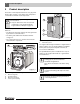
2 Product description 2 Product description The boiler is a low-temperature boiler for oil or gas power burners with constant or reset boiler water temperature control without minimum return temperature. NOTICE: Risk of system damage from use of incorrect burner. B Only use burners that meet the technical requirements of the oil/gas-fired boiler Logano G615 (Æ Chapter 3, page 11).
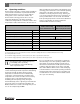
Product description Logano G615 Remark 2 Fuels Heating oil Liquid propane (LPG) Natural Gas (NG) The Logano G615 boiler can be operated with the specified fuels. Select a burner suitable for use with the fuels specified for the Logano G615 boiler. The output figures shown in the Tab. “Technical Data” are nominal power figures. Carry out maintenance and cleaning procedures annually. Check that the entire system is functioning correctly. Immediately remedy faults.
2 2.2 Product description Operating conditions Thermostream technology is a unique feature of Buderus cast iron boilers. Return water is preheated and mixed within the boiler before it comes in contact with the heating surface of the combustion chamber. The Thermostream technology ensures there is an even temperature distribution in the boiler and avoids condensate forming within the combustion chamber.
Product description 2.3 Compliance with standards and regulations Installation and operation of the system must comply with all applicable codes, regulations and statutory requirements. Installation, connection of the fuel supply and flue connector, commissioning, connection of the electrical power supply, servicing and repair may only be carried out by a trained and certified heating contractor. Only registered gas fitters may carry out work on the gas train.
2 2.
Specifications 3 3 Specifications The technical data provides information about the output profile of the Logano G615 . 6" (150 mm) 13 25/32" (350 mm) 50 7/16" (1281 mm) 4 59/64" (125 mm) LF VK EL 14 11/64" (360 mm) AA T 54 23/32" (1390 mm) 71 57/64" (1826 mm) 29 17/32" (750 mm) 62 27/32" (1596 mm) RK LK LG Fig. 3 AA EL LK LG RK VK 6 720 642 625-02.
3 Specifications Logano G615 Boiler capacity Unit Number of – boiler sections Nominal Btu/hr output 570 9 660 10 740 11 820 12 920 13 1020 14 1110 15 1200 16 1,743,604 – 1,944,921 1,948,333 – 2,252,014 2,255,426 – 2,524,984 2,528,397 – 2,797,956 2,801,368 – 3,139,170 3,142,582 – 3,480,385 3,483,797 – 3,787,477 3,790,889 – 4,094,570 (1111 – 1200) 4,053,624 – 4,425,548 (kW) (511 – 570) (571 – 660) 1,865,077 – 2,102,562 2,083,795 – 2,434,563 2,412,384 – 2,729,713 2,704,122 – 3,024,864 2,
Specifications Logano G615 Boiler capacity Unit Flue gas lbs./s mass flow rate oil, full (kg/s) load2) Flue gas mass flow rate, gas, partial load 60% Flue gas mass flow, gas, full load2) 3 570 0.5115 – 0.5765 660 0.5714 – 0.6676 740 0.6616 – 0.7487 820 0.7416 – 0.8296 920 0.8217 – 0.9308 1020 0.9218 – 1.0313 1110 1.0218 – 1.1228 1200 1.1118 – 1.2136 lbs./s (0.232 – 0.2615) 0.34 (0.2592 – 0.3028) 0.3935 (0.3001 – 0.3396) 0.4414 (0.3364 – 0.3763) 0.4883 (0.3727 – 0.4222) 0.5485 (0.4181 – 0.
4 4 Scope of delivery Scope of delivery The boiler can be delivered either as a pre-assembled block or in loose sections. 5 B After delivery, check all packaging for perfect condition. B Check the delivery for completeness. Use suitable equipment to transport the individual boiler sections (delivery as loose sections) and other individual parts. 4.
Positioning the boiler 6 Positioning the boiler This chapter describes how to properly position the Logano G615. Boiler assembly tool size 2.3 4 NOTICE: Risk of system damage from freezing. B Install the system in a room free from the danger of freezing. 6.1 5 L1 L2 L2 Tools and auxiliary materials The following tools and auxiliary materials are required for the boiler assembly (the listed items are not contained in the scope of delivery). • • • • • • • • • • • • • 6 Boiler assembly tool 2.
6 Positioning the boiler ≥≥ 15 15 3/4" 3/4" 50 7/16" 50 7/16" (1281 mm) (400 mm) (~ 1150 mm) Recommended wall clearances 45 45 1/4" 1/4" 6.2 Boiler capacity BTU/h (kW) Sections 1,944,921 – 9 – 12 2,797,956 (570 – 820) 3,139,170 – 4,094,570 13 – 16 Clearance A inch (mm) Recommended minimum 90 35/64" 55 1/8" (2300) (1400) 118 7/64" 59 1/16" (3000) (1500) (920 – 1200) Tab.
Positioning the boiler Installing the boiler on a boiler base or foundation (~ 50...100 mm) 1 34 34 3/4" 3/4" (~ 1160 mm) L2 16 9/64" 9/64" (410 mm) 32 9/32" 9/32" 32 (820 mm) 4" (~ 100 mm) 4" (100 mm) L2 (steel section) inch (mm) 57 7/8“ (1470) 64 9/16“ (1640) 71 1/4“ (1810) 77 61/64“ (1980) 84 41/64“ (2150) 91 11/32“ (2320) 98 1/32“ (2490) 104 23/32“ (2660) Tab. 9 Base dimensions for angle or sheet metal steel lengths 4" (100 mm) Fig.
7 Boiler block assembly 7 Boiler block assembly WARNING: Risk of injury from improperly secured boiler sections. B Use only suitable means of transportation when handling the boiler sections, e.g. a heavy duty hand truck with strap or a heavy duty hand truck. B Secure the individual boiler sections to prevent them from sliding off during transport. 5 7.1 Assembly of a boiler block from sections WARNING: Risk of injury from insufficiently secured boiler sections.
7 Boiler block assembly 7.2 Joining the boiler block assembly (delivery as loose sections) 1 Preparing boiler sections B Remove nuts and washers from the studs on the hubs of the boiler sections before attaching the rear section and front section. B Put the rear section in place and secure during assembly taking measures to prevent tipping over (Æ Fig 8 and separate instructions for installation). B File down any burrs on the hubs if necessary. 3 2 6 720 642 621-06.1o Fig.
7 Boiler block assembly B Do not let sealant rope overlap at the left and right of the butt joints (Æ Fig. 13, [3]). 1-3/4" (43 43 mm) 1 1-1/4" (32 mm) 32 2 6 720 642 625-09.1o Fig. 11 Driving nipples home 6 720 642 621-09.1o B Coat the packing grooves with adhesive (primer). Fig. 13 Inserting sealant rope 1 1 2 3 Packing grooves Sealant rope Butt joints Prepare the first intermediate section (with top supply connection): B File down any burrs on the hub.
7 Boiler block assembly B Evenly coat the hub sealing faces with sealant. B Coat the packing springs with primer. B Position the intermediate section with the supply connection so that the top and bottom hubs fit onto the nipples in the rear section. The directional arrow must point towards the rear. B Push mating flanges onto the tie rods and secure each with wedge. B Hold the tie rod in the center of the hubs and slightly draw together the compression tools using the clamping nut.
7 Boiler block assembly CAUTION: Danger of accident from material fatigue. Improperly used or poorly maintained assembly tools may fail. B Never work directly in front of the assembly tool while it is being tensioned. B Ensure that no one is standing in front of the assembly tool. B Release and remove the boiler assembly tool. B Check nipples are seated correctly. NOTICE: Assembly tool damage due to loose screw connections of the tie rods.
Boiler block assembly 7 B Remove boiler assembly tool. 2 3 1 2 6 720 642 625-17.1o 1 Fig. 20 Boiler block on pallet 6 720 642 625-16.1o Fig. 19 Inserting the tie rods 1 2 3 Tie rods (bottom) Tie rods (top) Tie rod with spring package The next step describes the installation of the supply pipe (Æ see Chapter 7.4, page 24). 7.3 Setting up the boiler block – (assembled block) DANGER: Risk of fatal injury from falling objects. B Provide a suitable means of supporting the load.
7 7.4 Boiler block assembly Inserting the supply pipe (parts crate) 7.5 For boilers with 9 – 11 sections, the supply pipe consists of 2 pieces, and 12 – 16 sections 3 pieces. B Push the flat gasket over the supply pipe. B Push the supply pipe from the front into the top boiler hub. B Close off with flange cover.
7 Boiler block assembly 7.6 Inserting the lower distribution tube (fittings crate) B Mount the tapped hole for the drain connection on the bottom boiler hub behind the flange (edge length 5 – 1/8" (130 mm)) with R ¾ ". B Fit customer-supplied boiler drain valve. The customer-supplied boiler fill and drain valve is only used as a drain valve here.
7 7.7 Boiler block assembly Leak test Conduct a leak test of the boiler block only when the boiler was delivered disassembled. Pre-assembled blocks are leak tested at the factory. For details of assembling the remainder of the boiler if the block is delivered pre-assembled Æ see Chapter 7.9.4, page 29. 7.7.1 Carrying out leak test 7.7.2 Seal leaks. If leaky hub connections are discovered during the pressure test, proceed as follows. B Remove supply pipe and lower distribution tube.
Boiler block assembly 7.8 Boiler water connections Please observe the following information regarding the boiler connection to the system of pipes. These instructions are important for trouble-free operation. NOTICE: Risk of system damage from leaking connections. B All pipe connections to the boiler must be free of stress and tension. NOTICE: System damage due to deposits, local overheating, and corrosion. B As a basic rule, clean and flush existing systems thoroughly before connecting new boiler.
7 Boiler block assembly 7.9 Installing draft diverter, baffles, and burner door The next step in the assembly process is to install the burner door and draft diverter. The pre-assembled boiler comes with these components already installed. 7.9.1 Positioning the draft diverter The GP sealant rope (fiberglass cord with silicon casing) which forms a seal is inserted in the draft diverter at the factory. 7.9.2 Screwing cleanout cover onto rear section Fig.
Boiler block assembly 7.9.3 Fitting burner door In the factory, the burner door is mounted with the hinges on the right hand side. For left-hand closing, remove the hinges from the right-hand side and reinstall them on the left-hand side of the burner door. 7.9.4 Inserting the flue gas baffles In pre-assembled boilers, the flue gas baffles are already fitted B Remove the cardboard transport protectors from the pre-assembled boiler.
7 Boiler block assembly 1 2 3 6 720 642 625-29.1o 6 720 642 625-30.1o Fig. 32 Insert the flue gas baffles (boiler block with 13 sections) Fig.
Boiler block assembly 2 V L10,H L9,H LV V LV 1 7 H H 4 V V L12,H L11,H LV LV 3 H H 6 V V L14,H LM L13,H LM LV LV 5 H H 8 V LM L16,H L15,H LM LV V LV 7 H H 6 720 642 625-32.1o Fig. 35 Thermal insulation for the various boiler sizes Item Æ Fig.
7 Boiler block assembly 7.10.2 Fitting the profile rails B Place top front profile rails onto the cast lugs and screw in place with machine screws (M8 × x 12). The folded edge on the front profile rail must face forward. B Place top rear profile rails onto the cast lugs and screw in place with machine screws (M8 × x 12). The folded edge of the rear profile rail must face rearward. B Place the side profile rails from the side on the front and rear profile rails and screw on with self-tapping screws.
7 Boiler block assembly B Close the slot below the flue outlet with spring hooks. Fig. 38 Fitting lower side profile rails and thermal insulation 1 2 3 4 5 Rear profile rail Rear section thermal insulation Spring hooks Bottom side profile rail Bottom side profile rail B Push rectangular thermal insulation onto the front top profile rail. B Fasten thermal insulation with 3 spring hooks.
7 Boiler block assembly B Mount rear base panel in the same way. Fig. 41 Mounting the side panel Fig. 40 Installation of the burner cable strain relief and base plates 1 2 3 Burner cable strain relief Bottom front profile rail Front base panel For the arrangement of the side panels and covers, please see Fig. 43, page 35.
Boiler block assembly 7 7.10.3 Fitting side panels and top covers B Fit all side panels as shown in the diagram. 1 2 LA LB LC LA LD LC A B C A D C 4 3 LA LE LE LC LA LE LB LC A E E C A E B C 5 6 LA LB LB LC LA LB LD LC A B B C A B D C 7 8 LA LD LD LC LA LE LD LE LC A D D C A E D E C 6 720 642 625-40.1o Fig.
7 Boiler block assembly B Fit all top covers as shown in the diagram. 1 2 LA LD LG LE LA LD LB LC LE A D G E A D B C E LA LD LB LG LE LA LD LB LC LB LE A D B G E A D B C B E LA LD LB LC LF LE LA LD LB LG LF LE A D B C F E A D B G F E LA LD LB LB LB LG LE LA LD LB LG LB LF LE A D B B B G E A D B G B F E 4 3 5 6 7 8 6 720 642 625-55.1o Fig.
7 Boiler block assembly B Push front top cover marked “A” with the hook in the slots of the side profile rail and push forward. B Screw back of top cover “A” to each side profile rail using one self-tapping screw. B Screw the top rear boiler to the back of the rear most top cover and side panels. B Screw the bottom rear boiler with the cut-out for the fill and drain connection down onto the side panels. 1 1 2 2 6 720 642 625-41.1o Fig. 45 Fitting the front top cover “A” 1 2 6 720 642 625-43.
8 8 Connecting the boiler on the flue gas side Connecting the boiler on the flue gas side This chapter describes how the boiler connections are made on the flue gas side. 8.1 Fitting the vent pipe sealing collar (accessory) We recommend you use a vent pipe sealing collar (Æ Fig. 49, [1]). B Push the vent pipe (Æ Fig. 49, [4]) as far as possible onto the draft diverter outlet (Æ Fig. 49, [6]). B Place the vent pipe sealing collar (Æ Fig. 49, [1]) around the vent pipe (Æ Fig.
Installing the control panel 9 Installing the control panel This section explains how to install a Logamatic 4000 series control panel and its set of temperature sensors. B Attach the base of the control panel to the top cover using two self-tapping screws. 1 DANGER: Risk to life from electric shock. B Electrical work may only be performed by professionals with appropriate qualifications.
9 Installing the control panel Connecting power supply Hard wire the control panel to the building power supply following recognized standards such as EN 50165 and local code, rules, and regulations. Mounting rear panel and terminal cover B If necessary, break away section from the rear panel. B Engage the lower hook of the rear panel section with the frame at an angle and tilt upward until the upper hooks engage with the side panels. B Put the top cover in place and tighten the screws.
Installing the control panel 9.2 9 B Push the control panel sensor TRK out of the sensor spacer by pressing it lightly. Installing set of temperature sensors NOTICE: Appliance damage from damaged capillaries. B Make sure that the capillaries are not crushed or otherwise compromised during unrolling and routing. FK STB B Route the capillaries through the cable duct and unroll to the required length.
10 10 Mounting the burner Mounting the burner This chapter explains how to install the burner. NOTICE: Damage to boiler due to incorrect burner. B Only use burners that conform to the technical requirements of the boiler (see Æ Chapter 3, page 11). 1 B Close the burner door and secure with 4 machine screws (M16 × 140) in the positions shown. Tighten the machine screws evenly crosswise.
System start-up 11 11 System start-up You can connect control panel of the 4000 series to the Logano G615. The commissioning process for the different types of control panels is the same. B Complete the commissioning log during the start-up process (Æ Chapter 11.5, page 45). NOTICE: Boiler damage from contaminated combustion air supply. B Ensure there is sufficient air supply. B Do not use or store any chlorinecontaining cleaning agents or halogenated hydrocarbons (e.g.
11 System start-up 11.2 Commissioning the system 11.4 Initial burner start-up B For commissioning, establish the required normal operating pressure. B Check that the flue gas baffles have been inserted correctly. B When commissioning the burner, follow the instructions in the technical documentation enclosed with the burner. B Complete the commissioning log for the burner. Details about the quality of the boiler water Æ operator's log NOTICE: Boiler damage due to temperature stresses.
System start-up 11 11.5 Commissioning log The Logano G615 can be used with an oil- or gas-fired burner. Fill in the commissioning log for the appropriate type of oil or gas burner carefully. B Sign all start-up work as completed and enter the relevant date. Commissioning operations 1. Perform leak test of the entire system Individual steps 2. Fill the heating system with water Æ page 43 3. Air purge the heating system 4. Perform the leak test if the boiler was assembled on site 5.
12 12 Shutting down the system Shutting down the system NOTICE: Risk of system damage from freezing. B The heating system can freeze up if it is disabled, e.g. shut down due to a fault. B Protect the heating system from freezing when temperatures below freezing are expected. Drain the boiler water from the heating system at its lowest point using the drain valve. To do this, open the air vent at the highest point in the system. 12.
13 System inspection and maintenance 13 System inspection and maintenance 13.1 General information Opening the boiler door Offer your customer a maintenance contract covering annual inspection and servicing work as required. To find out what a contract for annual inspection and demandbased servicing covers, refer to Chapter 13.7, page 52. DANGER: Risk of fatal injury from the explosion of flammable gases. B Work on gas components must be carried out by trained and certified personnel only.
13 System inspection and maintenance B Remove debris from the front and the cleanout openings on the rear section and on the draft diverter (Æ Fig. 61, page 48). B Check sealant ropes on the cleanout openings and burner door. Replace damaged or hardened sealant ropes. Appropriate sealant ropes are available from your local Buderus wholesaler. 3 6 720 642 625-49.1o 2 Fig. 60 Flue gas baffles, removing B Remove bottom boiler rear panel. B Loosen spring hooks below the flue outlet (Æ see Fig.
System inspection and maintenance K 13 G 5 A 4 8 6 720 642 625-54.1o Fig. 63 Cleaning brushes Number of sections Brush designation Brush size inch (mm) 9 - 11 4 2 61/64 × 4 21/64 (75 × 110) 2 23/64 × 2 7/8 (60 × 73) 7 7/8 × 3 5/32 (200 × 80) 12 -14 15 -16 5 8 Application Rod designation Flue gas passages A+K Combustion chamber A+G+K Length of the rods inch (mm) 78 47/64 (2000) 98 27/64 (2500) 78 47/64 + 39 3/8 (2000 + 1000) Tab.
13 System inspection and maintenance 13.4 Wet-cleaning the boiler When wet cleaning, pick the cleaning agent based on the degree of contamination (encrustations or soot). Proceed in the same sequence as if cleaning with cleaning brushes (Æ see Chapter 13.3, page 47). Follow the operating instructions of the cleaning agent and the cleaning brushes! Under some circumstances, it may be necessary to deviate from the procedure described here.
System inspection and maintenance 13.5 Checking the operating pressure The operating pressure must be at least 15 psi (1 bar). B Read the current operating pressure (psi) and temperature ( °C or °F) from the temperature/pressure gauge. B If the operating pressure drops below 15 psi (1 bar), ref boiler water. 13 13.6 Refilling boiler water and purging the system NOTICE: Risk of system damage from temperature stresses.
13 System inspection and maintenance 13.7 Inspection and maintenance logs The inspection and maintenance logs provide an overview of the required inspection and maintenance work. B Initial and date the inspection operations completed. The inspection and maintenance logs can also be used as templates. Inspection work 1. Check general condition of heating system 2. Visual inspection and function check of the heating system 3.
System inspection and maintenance Date:____________ Date:____________ Date:____________ 13 Date:____________ 1. 2. 3. 4. 5. 6. 7. 8. 9. 10. Company stamp/ signature Company stamp/ signature Company stamp/ signature Company stamp/ signature Tab.
13 System inspection and maintenance Additional maintenance work as-needed Page 1. Shut down the heating system Æ 46 2. Remove and clean heat exchanger baffles Æ 48 3. Clean the flue gas passages (heating surfaces) and flue gas baffles Æ 48 4. Clean the combustion chamber Æ 48 5. Clean the draft diverter Æ 48 6. Insert the flue gas baffles Æ 29 7. Check gaskets/sealant ropes on the burner and burner door and replace if required Æ 48 8. Commissioning the heating system Æ 43 9.
System inspection and maintenance Date:____________ Date:____________ Date:____________ 13 Date:____________ 1. 2. 3. 4. 5. 6. 7. 8. 9. 10. Company stamp/ signature Company stamp/ signature Company stamp/ signature Company stamp/ signature Tab.
14 14 Troubleshooting burner faults Troubleshooting burner faults Heating system faults are shown on the display of the control panel. You will find detailed information regarding fault displays in the service instructions for the relevant control panel. The burner fault is also indicated by a fault lamp on the burner. NOTICE: Risk of system damage from freezing. The heating system can freeze up in cold weather if it has been disabled due to a fault shutdown.
Spare parts 15 15 Spare parts B Request spare parts with name and part number using the spare parts list. NOTICE: Damage caused by use of spare parts not supplied by Buderus may not be covered under the manufacturer`s warranty. 2 1 3 6 5 4 9A 7 8 9B 6720906688.aa.RS-G615 Fig. 65 Spare part groups Logano G615 Item (Æ Fig.
15 Spare parts 18 17 11 18 20 9 19 14 7 8 11 14 10 11 14 1 12 4 16 16 6 12 5 18 12 16 18 2 17 25 27 23 20 26 21 19 22 20 3 2 24 15 23 13 3 22 20 6720906689.aa.RS-Kesselblock GE615 Fig.
Spare parts Item (Æ Fig. 66) 1 2 3 4 5 6 7 8 9 10 11 12 13 14 15 16 17 18 19 20 21 22 23 24 25 26 27 Designation Front section G615 Threaded stud DIN939 M16x45 5.6 Hexagon nuts ISO4032 M16 8 A3K Sealant rope 18x3800 GP Intermediate section G615 Intermediate section G615 VLO Gasket D160x206x1.
15 Spare parts View "A" "A" Ansicht View "A" turned 90° Ansicht "A" 90 gedreht 2 1 8 9 3 4 M8x12 31 5 20 23 22 21 6 12 25 M10x50 24 7 5 6 6 12 6 5 11 16 6 19 17 10 18 15 14 30 6720906690.aa.RS-Kesselblock GE615 Rückansicht Fig.
Spare parts Item (Æ Fig. 67) 1 2 3 4 5 6 7 8 9 10 11 12 14 15 16 17 18 19 20 21 22 23 24 25 30 31 Designation Rear section compl. G615 Threaded stud DIN939 M16x45 5.6 Washer DIN125-A17-A3K Hexagon nuts ISO4032 M16 8 A3K Threaded stud DIN939 M12x35 5.6 Hexagon nuts EN1661 M12 8.8 A3K Threaded stud DIN939 M12x45 5.8 Gasket D160x206x1.
15 Spare parts 7 10 7 8 6 9 8 1 2 2 5 1 5 3 4 5 40 3 5 Number of sections Number of flue gas baffles top left top right bottom left bottom right 2x sickle profile 2x sickle profile 2x sickle profile 2x sickle profile 2x sickle profile 2x sickle profile 2x sickle profile 2x sickle profile 2x sickle profile 2x sickle profile 2x sickle profile 2x sickle profile 1x wave profile 1x wave profile 2x sickle profile 2x sickle profile 2x sickle profile 2x sickle profile 1x wave profile 1x wave profile 1x
Spare parts Item (Æ Fig. 68) 1 2 3 4 5 6 7 8 9 10 Designation Flue gas baffle top sickle profile T1 Flue gas baffle top sickle profile T2 Flue gas baffle bottom sickle profile T1 Flue gas baffle bottom sickle profile T2 Flue gas baffle with wave profile Vent pipe G615-wt70S2 Thermal insulation vent pipe part 1+2 Thermal insulation vent pipe part 3+4 Vent pipe seal sleeve set DN360 Gasket for flue collar DN360 compl.
15 Spare parts 20 16 2 3 15 14 10 11 M5x16 M12x40 18 17 9 M10x25 8 St6,3x25 7 5 4 1 21 6720906692.aa.RS-Brennertür GE615 Fig.
Spare parts Item (Æ Fig. 69) 1 2 3 4 5 7 8 9 10 11 14 15 16 17 18 20 21 Designation Burner door compl. G615 Insulation ring burner door cpl. G615/SB735 Thermal insulation br door G615 Board607 Hex-head bolt M16x140 (DIN931), black Washer DIN125-A17-A3K Washer 6.4x20x1.25 A3K (10x) Burner plate 10x430x430 V1 ungeb verp Sealant rope 10x2000 GP Inspection hole cover plate cpl. Gasket D42x52x1.5mm Threaded pipe adapter GE 10-lr Ermeto Gasket D13.5x1mm Seal ring 13x18x1.
15 Spare parts 8 6 7 5 10 9 M8x12 1 4 M8x12 3 9 2 13 M8x12 10 M8x12 M8x12 M8x12 15 13 M8x12 5 9 14 M8x12 M8x12 15 6720906693.aa.RS-Verkleidung GE615 Grundbegestigung Fig.
Spare parts Item (Æ Fig. 70) Designation 1 Thermal insulation 80x280x1250mm 2 Thermal insulation 100x4700x420mm Thermal insulation 100x4700x590mm Thermal insulation 100x4700x760mm Thermal insulation 100x4700x930mm 3 Thermal insulation 100x4700x680 4 Thermal insulation 100x4700x1160mm 5 Retaining spring (10x) 6 Thermal insulation front cover left G615 7 Thermal insulation front cover right G615 8 Rear panel insulation G615 9 Profile rail compl. 1720mm long G615 Profile rail compl.
15 Spare parts 9 7 18 17 9 8 3 4 1 13 M8x12 2 14 12 M8x12 15 6720906694.aa.RS-Verkleidung GE615 St3,5x22 Fig.
Spare parts Item (Æ Fig. 71) 1 2 3 4 7 8 9 12 13 14 15 17 18 Designation Front cover G615 left cpl Front cover G615 right cpl Cover G615 cpl Logano G615 name plate Rear panel top G615 Rear panel bottom G615 Flat-head screw ST3.9x9.5 A3T (10x) Burner connection cable 170" (4300 mm) long compl. Connection terminal 7-pin green BR 1 burner Connector part ST18/7 silver-plated Cover clamp strain relief Cable clamp Flat-head screw ST3.9x9.
15 Spare parts Boiler capacity Side panels 1 3 1 5 4 1 2 1 2 5 3 3 1 3 1 5 2 1 1 Covers 5 3 4 4 2 5 5 4 4 5 2 5 6 9 12 10 6 7 8 10 9 10 6 9 7 12 6 9 7 8 7 10 6 9 7 8 11 10 6 9 7 12 6 9 7 7 7 6 9 7 12 11 10 12 7 10 11 10 6720906695.aa.RS-Verkleidung GE615 Anordnung Fig.
Spare parts Item (Æ Fig.
15 Spare parts 1 4 3 5 4 St4,8x19 11 2 St4,8x19 10 9 4 8 4 6720906696.aa.RS-Verkleidung Träger für Regelgerät Fig.
Spare parts Item (Æ Fig. 73) 1 2 3 4 5 8 9 10 11 Designation Side control panel bracket Base carrier for control panel Cover for control panel carrier Flat-head screw ST3.9x9.5 A3T (10x) Cover plate for control panel carrier Conduit shield (blue) Conduit slotted (blue) (1x) Top cover for HS 4311/4312 Burner cable 8M Installation material for control panel carrier 15 Order number 5097580 7079670 63045232 7 747 026 999 63045231 63045229 63045226 63045225 7079690 63045180 Tab.
Index Index A Assembly tool ........................................................................ 15 B Boiler conditions of use ........................................................ 7 F Fill water.................................................................................. 43 Fuels .......................................................................................... 7 I Inspection contract ..............................................................
Appendix Appendix Data and system handover Type ______________________ User ______________________ Manufacturer no. ______________________ Location ______________________ System installer ______________________ The system named above has been installed and commissioned according to standard engineering practice, as well as provisions of the buildings inspectorate and any legislative requirements. The technical documentation has been handed over to the user.
United States and Canada Bosch Thermotechnology Corp. 50 Wentworth Avenue Londonderry, NH 03053 Tel. 603-552-1100 Fax 603-584-1681 www.buderus.us U.S.A. Products manufactured by Bosch Thermotechnik GmbH Sophienstrasse 30-32 D-35576 Wetzlar www.buderus.com Bosch Thermotechnology Corp. reserves the right to make changes without notice due to continuing engineering and technological advances.