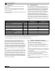
Low-temperature oil/gas boiler WARNING: If installation, adjustment, modification, operation or maintenance of the heating system is carried out by an unqualified person, this may result in personal injury or property damage. The directions of this installation manual must be followed precisely. If support or additional information is required, contact a qualified service company, service provider or the gas company.
Contents About this manual The appliance conforms to the basic requirements of the relevant directives. The conformity has been confirmed. The corresponding documentation and the original Declaration of Conformity are on file with the manufacturer. This installation and maintenance instructions contain important information for the safe and proper installation, initial start-up and maintenance of the oil/gas-fired boiler Logano G515. Contents 1 Guideline to symbols and safety instructions . . . . . . . .
Guideline to symbols and safety instructions 8 Connecting the boiler on the flue gas side . . . . . . . . . . . . . . . 31 8.1 Fitting the vent pipe sealing collar (accessory) . . . . . . 31 8.2 Installing a flue gas temperature sensor (accessory) . 31 1 1 Guideline to symbols and safety instructions 1.1 Guideline to symbols Warnings 9 Installing the control panel . . . . . . . . . . . . . . . . . . . . . . . . . . . . 32 9.1 Installing the control panel . . . . . . . . . . . . . . . . . . . . . .
1 1.2 Guideline to symbols and safety instructions Safety instructions Danger from failing to consider your own safety in an emergency such as a fire ▶ Never risk your own life. Your own safety must always take the highest priority. Risk due to oil leaks ▶ When using oil as the fuel, national regulations hold the operator responsible for immediately asking a specialist contractor to remedy oil leaks the moment they are discovered. If you smell gas ▶ Close the gas shut-off valve.
Product description 2 The Logano G515 oil/gas-fired boiler is supplied with or without a burner You can obtain undrilled or predrilled burner plates (hole pattern depends on burner) as accessories from Buderus. Product description 4 2 The predrilled burner plate is included in the scope of delivery for the Logano G515 with oil or gas-fired fan-assisted burners. 1 NOTICE: Risk of system damage from use of incorrect burner.
2 2.1 Product description Designated use 2.2 The Logano G515 oil/gas-fired boilers have been designed for the heating of water. The Logano G515 can be operated with oil, gas, and combination burners. For a list of the approved burners, please contact Bosch Thermotechnology Corp. This boiler can be operated with an aquastat, the Logamatic 4000, and other control systems. Operating conditions Thermostream technology is a unique feature of Buderus cast iron boilers.
Product description Installation of the wall mounted condensing gas boiler must comply with all applicable codes and regulations imposed by the national, Federal or local authorities and bodies. If no specific requirements are defined, in the USA, the latest edition of the National Fuel Gas Code ANSI Z223.1/ NFPA 54 applies. In Canada, installation must comply in all respects with the latest edition of the Installation Code for Gas Burning Appliances and Equipment, CAN/CSA-B.
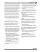
3 3 Specifications Specifications The technical data provides information about the output profile of the Logano G515. 2-23/64" 2 23/64" (60 mm) 38-9/16" 28 37/64" (980 mm) Ø ≤ 10-5/8" 10 5/8" (270 mm) VK 3-5/32" 3 5/32" (80 mm) (585 mm) 23-1/32" 23 1/32" RK 4-1/2" 4 1/2" (115 mm) 44-3/32" 44 3/32" (1120 mm) 51-49/64" 51 49/64" (1315 mm) (586 mm) 52-11/64" 52 11/64" (1325 mm) 61-1/4" 61 1/4" (1556 mm) 23-1/16" 23 1/16" 4-31/64" 4 31/64" (114 mm) EL 10" (250 mm) LK L Fig.
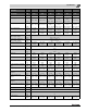
3 Specifications Logano G515 Boiler capacity Number of boiler sections Nominal output Unit 240 295 350 400 455 510 – 7 8 9 10 11 12 MBH 685.8 - 818.9 822.3 - 1.006.6 (241 – 295) 1.010.0 1.194.2 1.197.7 1.364.9 1.368.3 1.552.5 1.555.9 - 1.74.2 (201 – 240) (296 – 350) (351 – 400) (401 – 455) 1.080.3 1.286.7 1.278.2 1.465.9 1.461.8 1.669.2 (kW ) Combustion output MBH 735.7 - 886.1 879.7 - 1.088.5 (215.6 – 259.7) (257.8 – 319.0) (kW) (456 – 510) 1.665.8 1.869.2 (316.6 – 377.
4 Scope of delivery Logano G515 Boiler capacity Maximum permissible supply temperature3) Maximum permissible operating pressure Unit 240 295 350 400 °F 248 ( °C) (120) PSI 87 (bar) (6) 455 510 Table 4 1) Weight with packaging approx. 6–8% higher. 2) The details relate to the upper and lower rated output range. 3) Safety limit (high limit safety cut-out). Maximum possible supply temperature = safety limit (STB) – 32 °F (–18 K). Example: Safety limit (STB): = 212 °F (100 °C), max.
Positioning the boiler 6 Positioning the boiler This chapter describes how to properly position the Logano G515. NOTICE: Risk of system damage from freezing. ▶ Install the system in a room free from the danger of freezing. 6.
6 Positioning the boiler 38-9/16" 38 37/64" (980 mm) (400 mm) 2...4" ≥ 15-3/4" 15 3/4" 6.3 Installing the boiler on a boiler base or foundation (~ 50...80 mm) Recommended wall clearances 35-1/2" 35 1/2" (~ 900 mm) 6.2 33-1/2" 33 1/2" 1 (850 mm) LK L2 (AB+100 mm) L1 AB + 4" A 4" (100 mm) 21-1/4" 21 1/4" (540 mm) 6 720 642 623-04.1o Fig. 6 Fig. 7 3-1/2" 3 1/2" (~ 90 mm) AB 6 720 642 623-05.
Boiler block assembly 7 7.1 Boiler block assembly 6 Assembly of a boiler block from sections WARNING: Risk of injury from inadequately secured boiler sections. ▶ Secure boiler sections during assembly and take measures to prevent them from tipping over. The installation aid (accessory) is available from Buderus on request. WARNING: Risk of injury from improperly secured boiler sections. ▶ Use only suitable means of transportation when handling the boiler sections, e.g.
7 7.2 Boiler block assembly Joining the boiler block assembly (delivery as loose sections) Remove nuts and washers from the studs on the hubs of the boiler sections before attaching the rear section and front section. ▶ File down any burrs on the hubs ( Fig. 12). ▶ Clean the packing grooves where required using a wire brush and cloth ( Fig. 13, [3]). If you are using the installation aid, you will need to remove the cleaning access cover before you can attach it to the rear section.
7 Boiler block assembly 1 1 3 2 6 720 642 621-06.1o 6 720 642 621-08.1o Fig. 13 Prepare packing grooves and hubs Fig. 15 Coat the packing grooves with adhesive (primer) The next step involves preparing the nipples that will eventually seal the boiler sections. ▶ Clean nipple with a rag soaked in solvents or gasoline and coat evenly with sealant. ▶ Insert the nipple straight into the upper (Sz. 4.181.70) and lower (Sz.
7 Boiler block assembly The packing springs must be clean and dry. Clean if necessary. ▶ Clean the hub sealing faces with a rag soaked in solvents or gasoline. ▶ Evenly coat the hub sealing faces with sealant ( Fig. 17, [1]). ▶ Coat the packing springs with primer ( Fig. 17, [2]). 1 Before the nipples are inserted in the next intermediate section, the part-assembled boiler block must be compressed using the boiler assembly tool.
Boiler block assembly 7 Use a size 2.2 or 2.3 boiler assembly tool ( Fig. 4, Fig. 5 and Fig. 20 [1 and 2]). ▶ Push pressure flanges ( Fig. 20, [3]) with clamping nuts onto the tie rods ( Fig. 4, page 11 and Fig. 5, [4]). ▶ Push a tie rod through the upper and lower hubs on the boiler. ▶ Push mating flanges onto the tie rods and secure each with wedge (dowel pin for assembly tool 2.2).
7 Boiler block assembly 7.4 2 3 Inserting the supply pipe (parts crate) The supply pipe ( Fig. 24, [4]) consists of 2 pieces for boilers with 10 – 12 boiler sections. ▶ Push the flat gasket over the supply pipe ( Fig. 24, [1]). ▶ Push the supply pipe from the front into the top boiler hub. ▶ Close off with flange cover ( Fig. 24, [2]). The supply pipe must be fixed in such a way that the holes on the supply pipe are positioned at the correct angle.
Boiler block assembly 7.6 7 Leak test Conduct a leak test of the boiler block only when the boiler was delivered disassembled. Pre-assembled sections are leak tested in the factory. 1 For details of assembling the remainder of the boiler if the block is delivered pre-assembled, see Chapter 10, page 34. 7.6.1 Carrying out leak test NOTICE: Risk of system damage from overpressure. ▶ Ensure that no pressure, control or safety equipment is fitted during leak tests.
7 7.7 Boiler block assembly Boiler water connections 7.8 Please observe the following information regarding the boiler connection to the system side. These instructions are important for trouble-free operation. NOTICE: Risk of system damage from leaking connections. ▶ All pipe connections to the boiler must be free of stress and tension. NOTICE: System damage from deposits, local overheating, and corrosion. ▶ As a basic rule, clean and flush existing systems thoroughly before connecting the new boiler.
Boiler block assembly 7.8.3 Fitting the burner door ▶ Place a few drops of Silastic adhesive 6 inches – 8 inches (15 – 20 cm) apart in the packing grooves ( Fig. 31, [2]) on the front section ( Fig. 31). ▶ Insert GP sealant rope into the packing groove on the front section. The sealant rope joint should be located at the side ( Fig. 31, [2]). 5 7 6 5 1 2 1 4 3 2 6 720 642 623-30.1o Fig. 32 Hooking in the burner door 4 3 7.8.
7 Boiler block assembly 7.8.5 7.9 Insert the flue gas baffle plates In pre-assembled boilers, the flue gas baffles are already fitted. ▶ Remove the cardboard transport protectors from the pre-assembled boiler. Installation of the boiler jacket This section describes how to install thermal insulation and jacket components. ▶ You must install the cross rails and longitudinal rails before installing the thermal insulation in order to be able to align the brackets correctly.
Boiler block assembly 1 Right and left-hand installation on... Front section Section no. Intermediate section Section no. Rear section Section no. 7 1 4 7 8 1 4 8 9 1 5 9 10 1 5 10 11 1 4 and 7 11 12 1 4 and 8 12 Total number of boiler sections 7 2 Table 12 7.9.2 Fitting the profile rails ▶ Fasten top front crosswise profile rails ( Fig. 37, [2]) to the cast lugs ( Fig. 37, [1 and 4]) and screw on hand-tight with hexagon bolts (M8 × 16).
7 Boiler block assembly ▶ Align the longitudinal rails, screw on the brackets at the front and/or rear section ( Fig. 40, [1 and 3]) and fully tighten. ▶ Push the center brackets ( Fig. 40, [2]) against the longitudinal rails from below, then screw onto the boiler block and tighten. 1 2 3 6 720 642 623-38.1o Fig. 40 Aligning the longitudinal rails 7.9.3 Fitting the thermal insulation First of all, take the longitudinal rails off to install the thermal insulation.
Boiler block assembly 2 V L8 V L7 1 7 H H 4 V V L10,H L9 L10,V 3 H H 6 V V L12,H L11,H L12,V L11,V 5 H H 6 720 642 623-40.1o Fig.
7 Boiler block assembly ▶ Fit rectangular thermal insulation ( Fig. 44. [1]) with the cut-outs facing upwards at the front above the door. ▶ Fasten thermal insulation to the block thermal insulation with the 3 spring hooks ( Fig. 44, [2]). 2 2 1 3 2 1 1 3 6 720 642 623-44.1o Fig. 46 Fitting the thermal insulation for the rear section 6 720 642 623-42.1o Fig. 44 Installing thermal insulation at the front ▶ Push longitudinal rails ( Fig.
Boiler block assembly 7 7.9.4 Fitting side panels and top covers ▶ Fit all side panels as shown in the diagram ( Fig. 48). 1 K 3 LA LA A A K 2 5 LA LC LA A C A K 4 LB B B LC LC LA A C C A LB LC LC LB B C C B 6 LB LC LB B C B 6 720 642 623-46.1o LB LA K K K Fig.
7 Boiler block assembly To fit the side panel sections, the side panel flaps must first be fastened to the front side panels. ▶ Fasten the hinges to the side panel flaps beforehand using 2 selftapping screws in each case. ▶ Hook the hinge pins ( Fig. 49, [1]) on the side panel flap into the cut-out of the front side panel and secure with self-tapping screws. ▶ Attach tension spring ( Fig. 49, [2]) to the side panel and side panel flap. ▶ Push the base rails that run crosswise ( Fig.
7 Boiler block assembly ▶ Push the center boiler cover with the folded edges ( Fig. 53, [1]) under the front boiler cover and insert into the bead of the side panels. 1 1 2 6 720 642 623-53.1o Fig. 55 Fitting the rear boiler panel 6 720 642 623-51.1o Fig. 53 Fitting the center cover ▶ Fit the rear boiler cover on the side panels with the folded edges and cut-out for the heating circuit flow ( Fig. 54, [1]) facing toward the front.
7 Boiler block assembly ▶ Snap burner cable with strain relief into cable entry ( Fig. 57, [1]). ▶ Insert the burner cable with strain relief into the burner door cladding. ▶ Route the burner cable up along the folded edge of the burner door cladding and fasten with the cable clamp to ensure the burner cable does not come into hot components of the boiler. ▶ Fit the burner door cladding on the burner door from the front and screw on with four machine screws ( Fig. 57, [2 to 5]).
Connecting the boiler on the flue gas side 8 Connecting the boiler on the flue gas side This chapter explains how to connect the boiler on the flue gas side. 8.1 Fitting the vent pipe sealing collar (accessory) We recommend you use a vent pipe sealing collar ( Fig. 59, [1]). 8.2 8 Installing a flue gas temperature sensor (accessory) ▶ Weld a sleeve ( Fig. 59, [3]) at a distance of 2 × vent pipe diameters (A) from the draft diverter ( Fig. 59, [6]) in the vent pipe ( Fig. 59, [4]).
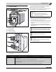
9 9 Installing the control panel Installing the control panel This section explains how to install a Logamatic 4000 series control panel and its set of temperature sensors. 9.1 Installing the control panel Fig. 60 shows the control panel and the top cover “A” from the back. ▶ Loosen both screws on top of the control panel ( Fig. 60, [1]) and remove the top cover. ▶ Mounting the control panel in place Fit the control panel at the front by inserting the alignment tabs ( Fig.
Installing the control panel 9 1 2 6 720 642 623-62.1o 6 720 642 623-60.1o Fig. 65 Boiler with fitted control panel Fig. 63 Making the electrical connections ▶ Connect the electrical cables as shown in the wiring diagram. Take care to ensure proper cable and capillary tube routing. Secure all cables with cable strain reliefs. ▶ Insert cable strain relief with cable inside into the frame and secure by closing the lever ( Fig. 64, [1]). 1 6 720 642 623-61.1o Fig.
10 10 Mounting the burner Mounting the burner This chapter explains the basic steps involved in fitting a burner NOTICE: Risk of system damage from use of incorrect burner. ▶ Only use burners that meet the technical requirements of the oil/gas-fired boiler Logano G515 ( Chapter 3, page 8). ▶ Close the burner door and seal with 4 machine screws (M16 × 140) ( Chapter 7.8.3, page 21, Fig. 32, [3 to 6]). Tighten the machine screws evenly crosswise.
System start-up 11 11.1 System start-up Filling the system NOTICE: Risk of system damage from temperature stresses. ▶ During operation, only fill the heating system via the fill valve on the system side (return). You can connect control panels of the 4000 series to the Logano G515. The commissioning process for the different types of control panel is the same. NOTICE: The boiler can be damaged through heavy dust deposits! ▶ Do not operate the boiler where heavy dust contamination persists, e.g.
11 11.5 System start-up Raising flue gas temperature With a new boiler, the flue gas temperature when the boiler temperature is 176 °F (80 °C) will be around 320 – 356 °F (160 – 180 °C), depending on the boiler rating. In two-stage operation the temperature of the flue gas is lower. You can increase the flue gas temperature further by removing individual hot gas check plates and hot gas baffle plates or combinations of these.
System start-up 11.6 11 Commissioning log The Logano G515 can be used with an oil or gas-fired burner. Fill in the commissioning log for the appropriate type of oil or gas burner carefully. Commissioning operations 1. Perform leak test of the entire system 2. Fill the heating system with water 3. Purge the air from the heating system 4. Perform the leak test if the boiler was assembled on-site 5.
12 12 Shutting down the system Shutting down the system You can connect control panels of the 4000 series to the Logano G515. The shutting down process for the different types of control panel is the same. NOTICE: Risk of system damage from freezing. ▶ The heating system can freeze up if it is disabled, e.g. shut down due to a fault. ▶ Protect the heating system from freezing when temperatures below freezing are expected.
System inspection and maintenance 13 System inspection and maintenance 13.1 General information Offer your customer a maintenance contract covering annual inspection and servicing work as required. To find out what a contract for annual inspection and demand-based servicing covers, refer to Chapter 13.7, page 42. 4 13 1 DANGER: Risk of fatal injury from the explosion of flammable gases. ▶ Work on gas components must be carried out by trained and certified personnel only.
13 System inspection and maintenance 1 2 1 3 6 720 642 623-69.1o 3 2 Fig. 73 Cleaning brushes 6 720 642 623-71.1o ▶ Clean the flue gas passages, starting at the front and working toward the back with cleaning brushes 1 and 2 ( Fig. 74, [1 and 3]). ▶ Clean the rear wall of the combustion chamber with cleaning brush 3. ▶ Clean the rest of the combustion chamber ( Fig. 74, [2]) with cleaning brush 2. Fig. 75 Removing the cleanout cover.
System inspection and maintenance 13.4 Wet-cleaning the boiler 13.6 When wet-cleaning, pick the cleaning agent based on the level of contamination. Proceed with wet cleaning in the same order as described for cleaning with cleaning brushes ( Chapter 13.3, page 39). For wet-cleaning (chemical cleaning), observe the operating instructions of the relevant cleaning equipment and cleaning agent. It may be necessary to vary the wet-cleaning process from that described here.
13 13.7 System inspection and maintenance Inspection and maintenance logs The inspection and maintenance logs provide an overview of the required inspection and maintenance work. Inspection work 1. Check general condition of heating system 2. Visual inspection and function check of the heating system 3. Check fuel and water-carrying components of the system for: • Leaks during operation • Visible signs of corrosion • Signs of aging 4.
System inspection and maintenance Date:____________ Date:____________ Date:____________ Date:____________ Company stamp/signature Company stamp/signature Company stamp/signature Company stamp/signature 13 1. 2. 3. 4. 5. 6. 7. 8. 9. 10.
13 System inspection and maintenance Additional maintenance work as-needed Page 1. Shut down the heating system 38 2. Remove and clean heat exchanger baffles 39 3. Clean the flue gas passages (heating surfaces) and flue gas baffles 40 4. Clean the combustion chamber 40 5. Clean the draft diverter 40 6. Insert the flue gas baffles 40 7. Check gaskets/sealant ropes on the burner and burner door and replace if required (see burner documentation) 8.
Troubleshooting burner faults 14 14 Troubleshooting burner faults Heating system faults are shown on the display of the control panel. You will find detailed information regarding fault displays in the service instructions for the relevant control panel. The burner fault is also indicated by a fault lamp on the burner. NOTICE: Risk of system damage from freezing. The heating system can freeze up in cold weather if it has been disabled due to a fault shutdown.
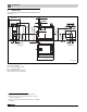
15 15 Spare Parts Spare Parts ▶ Request spare parts with name and part number using the spare parts list. 2 1 3 6 5 4 8 7 6720906661.aa.RS-G515 Fig. 78 Spare part groups Logano G515 Item ( Fig.
Spare Parts 15 View "A" "A" Ansicht 62 64 65 63 59 M12x40 58 59 61 M12x40 View "A" turned 90°gedreht Ansicht "A" 90 63 43 62 M12x40 16 61 17 64 58 19 24 23 27 18 26 65 25 48 50 20 20 28 21 22 51 19 45 44 21 53 22 19 48 23 27 21 26 54 55 54 22 47 25 24 52 71 57 53 21 70 56 49 28 55 56 54 22 46 55 57 54 55 6720906654.aa.RS-Kesselblock-hinten G515 Fig.
15 Spare Parts Item ( Fig. 79) Designation 1 Boiler block unassembled – 7 segments 5 086 720 Boiler block unassembled – 8 segments 5 086 722 Boiler block unassembled – 9 segments 5 086 724 Boiler block unassembled – 10 segments 5 086 726 Boiler block unassembled – 11 segments 5 086 728 Boiler block unassembled – 12 segments 2 Front segment G515 Order number 5 086 730 8 718 572 188 0 3 Studs DIN939 M12x35 5.
Spare Parts Item ( Fig. 79) Designation 31 Gasket D72x96x1.5mm 15 Order number 8 718 571 260 0 45 Sealant graphite treated with linseed oil 450 g can 46 Primer 181, 12.
15 Spare Parts View "A" "A" Ansicht 62 64 65 63 59 M12x40 58 59 61 M12x40 View "A" turned Ansicht "A" 9090° gedreht 63 43 62 M12x40 16 61 17 64 58 19 24 23 27 18 26 65 25 48 50 20 20 28 21 22 51 19 45 44 21 53 22 19 48 23 27 21 26 54 55 54 22 47 25 24 52 71 57 53 21 70 56 49 28 55 56 54 22 46 55 57 54 55 6720906654.aa.RS-Kesselblock-hinten G515 Fig.
Spare Parts Item ( Fig. 80) Designation 16 Threaded stud DIN939 M16x45 5.6 17 Washer DIN125-A17-A3K 3 869 840 18 Hexagon nuts ISO4032 M16 8 A3K 82 585 200 19 Threaded stud DIN939 M12x35 5.6 3 719 184 20 Threaded stud DIN939 M12x60 5.
15 Spare Parts 7 2 3 4 22 13 12 14 10 11 10 16 18 15 17 8 21 19 ST6,3x25 3 M12x40 6 5 25 1 20 6720906655.aa.RS-Brennertür G51 Fig.
Spare Parts Item ( Fig. 81) Designation 1 Burner door compl. G515 2 Sealant rope 18x2900mm long (for burner door) 63 020 973 3 Thermal insulation br door G515 Board607 63 002 424 4 Insulating shield G505/G515/SB605/SB615 63 004 307 5 Hinge eyelet painted G515 5 327 430 6 Washer DIN125-A13-A3K 5 883 276 7 Insulation ring burner door G515 isoglas 5 333 046 8 Washer DIN9021 A6,4 A3K 5 264 166 10 Gasket D42x52x1.5mm 5 752 520 15 Order number 63 015 444 11 Glass pane D49.
15 Spare Parts M8x20 11 13 M8x20 13 10 6 9 8 9 9 2 3 15 9 14 7 9 14 1 14 2 14 3 14 15 16 2 3 4 17 11 17 9 3 5 2 16 17 6720906656.aa.RS-Verkleidung-Befestigung G515 Fig.
Spare Parts Item ( Fig. 82) Designation 1 Bottom profile rail G515 2 Washer DIN125 A8.4 A3K (10x) 3 Hex-head bolt ISO4017 M8x16 8.8 5 090 124 4 Base left compl. 1315mm long 5 078 642 Base left compl. 1485mm long 5 078 644 Base left compl. 1655mm long 5 078 646 Base left compl. 1825mm long 5 078 648 Base left compl. 1995mm long 5 078 650 Base left compl. 2165mm long 5 078 652 Base right compl. 1315mm long 5 078 630 Base right compl. 1485mm long 5 078 632 Base right compl.
15 Spare Parts side panel Seitenwände / side panel segments Glieder / segments 7 8 9 cover Abdeckungen / cover segments Glieder / segments 7 8 9 10 11 12 Pos. 12 13 14 10 11 12 Pos. A 614mm 699mm 339mm B C 4 4 4 2 17 18 4 4 2 4 4 4 509mm 339mm 1 1 2 0 1 2 2 1 1 3 2 2 28 19 16 12 13 17 18 20 14 15 21 12 13 22 23 28 11 12 13 28 27 8 9 12 13 1 29 28 28 2 6 10 M6x12 28 4 14 11 7 25 24 28 26 10 M6x12 3 5 M6x12 8 9 14 6720906657.aa.
Spare Parts Item ( Fig. 83) Designation 1 Front cover II G515 63 029 196 2 Conduit shield (blue) 63 045 229 3 Front cover rt G515 63 029 193 4 Conduit slotted (blue) (1x) 63 045 226 5 Cover bott cpl G515 5 078 714 6 Cover top cpl G515 5 078 712 7 Appliance label Buderus Logano G515 (>4/1999) 67 902 827 15 Order number Appliance label Logano plus G515 (>4/1999) 67 902 849 8 Flap cpl G515 5 078 690 9 Thermal insulation f.
15 Spare Parts 5 4 3 2 1 6720906658.aa.RS-Untergestell G515 Fig.
Spare Parts Item ( Fig. 84) Designation 1 Sound-absorbing boiler base for G515. Sz 240 5 093 400 Sound-absorbing boiler base for G515. Sz 295 5 093 402 Sound-absorbing boiler base for G515. Sz 350 5 093 404 Sound-absorbing boiler base for G515. Sz 400 5 093 406 Sound-absorbing boiler base for G515. Sz 455 5 093 408 2 15 Order number Sound-absorbing boiler base for G515.
15 Spare Parts 17 10 11 16 30 30 12 30 10 30 9 30 30 14 14 30 19 30 18 30 30 30 30 30 8 30 30 30 30 7 4 30 30 20 22 21 28 23 1 30 30 M6x12 M6x12 25 25 29 26 M6 M6 6720906659.aa.RS-Schalldämpfer G515 Fig.
Spare Parts Item ( Fig. 85) Designation 1 Bottom compl. 790x885mm size 1.1 (type 1.2) 5 414 718 Bottom compl. 820x1165mm (type 2.2) 5 414 770 4 7 8 Order number Front cover compl. 570x700mm (type 1.2) 5 414 683 Front cover compl. 730x750mm (type 2.2) 5 414 780 Baffle compl. 530x795mm (type 1.2) 5 414 688 Baffle compl. 670x825mm (type 2.2) 5 414 784 Side panel left compl. 650x890mm (type 1.2) 5 414 776 Side panel left compl. 830x1170mm (type 2.2) 5 414 778 9 Cover bottom cpl 2x50.
15 Spare Parts 5 4 4 7 10 10 12 9 10 10 1 11 3 10 6 M6 2 4 4 8 6720906660.aa.RS-Sicherheitsgruppe G515 Fig.
Spare Parts Item ( Fig. 86) Designation 1 Cap valve with drain & fill valve 5 639 600 2 OV pressure gauge block valve 1/2"AG, PN250, 81 504 600 3 Röhrenfeder pressure gauge d: 100mm, 0-10bar 81 188 605 4 Set of grommets for safety armatures 5 639 660 5 Pressure regulator cpl minimal f.
Index Index A Added water ........................................................ 35 Assembly tool ....................................................... 11 P Positioning .......................................................... 20 Preparing ............................................................ 16 Product description .................................................. 5 B Boiler capacity ........................................................ Boiler conditions of use ...........................
Appendix Appendix Data and system handover Type ______________________ User ______________________ Manufacturer no. ______________________ Location ______________________ System installer ______________________ The system named above has been installed and commissioned according to standard engineering practice, as well as provisions of the buildings inspectorate and any legislative requirements. The technical documentation has been handed over to the user.
Appendix 66 Logano G515 – 6 720 647 208 (2014/09)
Appendix Logano G515 – 6 720 647 208 (2014/09) 67