
Install Instructions
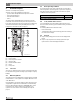

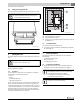


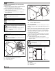
Table Of Contents
- Contents
- 1 Safety considerations
- 1.1 Key to symbols
- 1.2 Safety instructions
- 2 Product Description
- 3 Dimensions and Connections
- 4 Scope of delivery
- 5 Moving the boiler
- 6 Placing the boiler
- 7 Boiler installation
- 8 Check openings for combustion air supply and venting
- 9 Requirements for connection to chimneys or venting systems
- 10 Flue pipe installation
- 11 Placing the heating system in operation
- 12 Final start-up procedures
- 13 Start-up protocol
- 14 Taking the heating system out of operation
- 15 Boiler inspection and maintenance
- 15.1 Why is regular maintenance important?
- 15.2 Testing the flue system, including combustion air, air inlets and Ventilation openings
- 15.3 Inspection of the boiler and burner
- 15.4 Preparing boiler for cleaning
- 15.5 Cleaning the boiler
- 15.6 Cleaning the burner
- 15.7 Maintenance protocol
- 15.8 Troubleshooting the GC 144 II
- 16 Technical specifications
- 17 Electrical circuit diagrams

3
Dimensions and Connections
Logano GC 144 II – 6 720 808 893 (2014/04) 5
3 Dimensions and Connections
Fig. 2 Back, side and front view, measurements in inches
* optional connection
VK Boiler supply
RK Boiler return
EL Boiler drain
GAS Gas connection
Dimensions
Fig. 3 Pressure drop/boiler
2
3/8
RK 1¼"
VK 1¼"
GAS ½"
EL ¾"
(GAS ½")*
6 720 804 440-02.1T
Boiler size Boilerinput A B
Vent
connection II
Min. relief
valve capacity
Number of
Orifices
Water volume Dry weight
Btu/hr Inches Inches Inches lb/hr Qty. US Gal. lbs
18/3 74000 13 1/8" 8" 5" 62 2 2.4 228
25/4 103000 16 3/4" 8 2/3" 5" 86 3 2.9 287
32/5 132500 20 3/8" 9 1/2" 6" 110 4 3.4 349.5
Table 3 Dimensions/specs for GC 144 II
For the size and dimensions of the main gas orifices,
refer to chapter 16, page 29.
6 720 804 440-03.1T