
Install Instructions


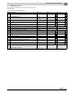

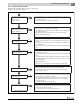

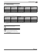


Table Of Contents
- Contents
- 1 Safety considerations
- 1.1 Key to symbols
- 1.2 Safety instructions
- 2 Product Description
- 3 Dimensions and Connections
- 4 Scope of delivery
- 5 Moving the boiler
- 6 Placing the boiler
- 7 Boiler installation
- 8 Check openings for combustion air supply and venting
- 9 Requirements for connection to chimneys or venting systems
- 10 Flue pipe installation
- 11 Placing the heating system in operation
- 12 Final start-up procedures
- 13 Start-up protocol
- 14 Taking the heating system out of operation
- 15 Boiler inspection and maintenance
- 15.1 Why is regular maintenance important?
- 15.2 Testing the flue system, including combustion air, air inlets and Ventilation openings
- 15.3 Inspection of the boiler and burner
- 15.4 Preparing boiler for cleaning
- 15.5 Cleaning the boiler
- 15.6 Cleaning the burner
- 15.7 Maintenance protocol
- 15.8 Troubleshooting the GC 144 II
- 16 Technical specifications
- 17 Electrical circuit diagrams

17
Electrical circuit diagrams
Logano GC 144 II – 6 720 808 893 (2014/04) 31
Fig. 44 Wiring Diagram– GC 144 II
6 720 804 440-72.1TT
US
Blocked
vent switch
B1
1
K1
W
R
T-Stat
C1
L1
K2
M
Transformer
3
4
2
green
blue
white
red
Circulator
To Pilot
Burner
Spark
Gas valve
MainPilot
PV
PV
MV
GND
MV
S8600H
GND
PV
PV/MV
MV
24V
24VGND
K1
TR High
Limit
Flame roll out
safety
shutoff switch
K2
B2
L2
N
L
24V AWG 18 WIRE
120 VAC
Wiring Schematic GC 124 / GC 144
Wire nut
Wire nut
Wire nut
Circuit breaker
Emer
gency shut-off switch
Fuse
1,25AT
Page: 2/2
Wiring diagram gas-boiler GC124 USA / GC 144 USA
Intermittent ignition
8469
8718588198
2012/11
GAW 032 USA
Drwg. no.:
Reviewed :
Edition :
Wiring diagram :