
Install Instructions

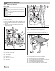


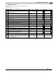

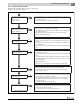

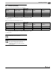

Table Of Contents
- Contents
- 1 Safety considerations
- 1.1 Key to symbols
- 1.2 Safety instructions
- 2 Product Description
- 3 Dimensions and Connections
- 4 Scope of delivery
- 5 Moving the boiler
- 6 Placing the boiler
- 7 Boiler installation
- 8 Check openings for combustion air supply and venting
- 9 Requirements for connection to chimneys or venting systems
- 10 Flue pipe installation
- 11 Placing the heating system in operation
- 12 Final start-up procedures
- 13 Start-up protocol
- 14 Taking the heating system out of operation
- 15 Boiler inspection and maintenance
- 15.1 Why is regular maintenance important?
- 15.2 Testing the flue system, including combustion air, air inlets and Ventilation openings
- 15.3 Inspection of the boiler and burner
- 15.4 Preparing boiler for cleaning
- 15.5 Cleaning the boiler
- 15.6 Cleaning the burner
- 15.7 Maintenance protocol
- 15.8 Troubleshooting the GC 144 II
- 16 Technical specifications
- 17 Electrical circuit diagrams

15
Boiler inspection and maintenance
Logano GC 144 II – 6 720 808 893 (2014/04)28
Fig. 42 Troubleshooting the GC 144 II
START
Room thermostat (control) signals heat requirement
Vent damper (if installed) opens.
Ignition spark generator operates
• ignition gas valve opens.
Pilot flame stand by
• ignition spark generator stops.
• main gas solenoid valve opens.
Main burner operation
• pilot assembly monitors ignition flame.
Specified thermostat value (control) reached
Main and ignition gas valves close, gas burners ex-
tinguished, vent damper (if installed) closes.
Ignition burner operation
Ignition flame burns, automatic
ignition signals steady ignition
flame.
or ignition flame does not burn,
pilot assembly starts ignition at-
tempt, switches off after 90
seconds.
END
PHASE 1
Ignition attempt
PHASE 2
Main burner
operating
Power interruption
System switches off. Does
the system restart when
power is restored?
Pilot flame fault
Main gas valve closes,
ignition module starts
ignition attempt.
6 720 804 440-5
3