
Install Instructions

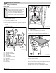


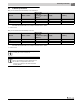

Table Of Contents
- Contents
- 1 Safety considerations
- 1.1 Key to symbols
- 1.2 Safety instructions
- 2 Product Description
- 3 Dimensions and Connections
- 4 Scope of delivery
- 5 Moving the boiler
- 6 Placing the boiler
- 7 Boiler installation
- 8 Check openings for combustion air supply and venting
- 9 Requirements for connection to chimneys or venting systems
- 10 Flue pipe installation
- 11 Placing the heating system in operation
- 12 Final start-up procedures
- 13 Start-up protocol
- 14 Taking the heating system out of operation
- 15 Boiler inspection and maintenance
- 15.1 Why is regular maintenance important?
- 15.2 Testing the flue system, including combustion air, air inlets and Ventilation openings
- 15.3 Inspection of the boiler and burner
- 15.4 Preparing boiler for cleaning
- 15.5 Cleaning the boiler
- 15.6 Cleaning the burner
- 15.7 Maintenance protocol
- 15.8 Troubleshooting the GC 144 II
- 16 Technical specifications
- 17 Electrical circuit diagrams

15
Boiler inspection and maintenance
Logano GC 144 II – 6 720 808 893 (2014/04) 23
15.5.2 Wet cleaning (chemical cleaning)
For wet cleaning use a suitable cleaning agent depending on the degree
of build-up of dirt (soot or scale).
Use the same procedure as described for cleaning with brushes
( chapter 15.5.1, page 22).
▶ Cover control with foil to prevent entry of spray into the control.
▶ Ventilate boiler room well during cleaning.
▶ Spray flue gas vents evenly with the cleaning agent.
▶ Replace and install the burner in reverse order of removal and
disassembly.
▶ Place the heating system in operation.
▶ Heat the boiler water to a temperature of at least 122°F.
▶ Take the boiler out of operation.
▶ Allow boiler to cool.
▶ Remove burner.
▶ Brush out flue gas passages.
▶ Clean combustion chamber and bottom insulation.
▶ Continue to ventilate boiler room well.
▶ Install burner.
▶ Reattach boiler jacket.
Fig. 37 Clean out the gas passages
[1] Cleaning brush
[2] Insulation
[3] Foil
Fig. 38 Wet cleaning boiler
15.6 Cleaning the burner
▶ Remove burner ( chapter 15.5.1, page 22).
▶ Check burner rods for dirt. If necessary, clean burner as described
below.
▶ Unscrew ignition burner unit from burner.
▶ Disconnect ignition gas line from ignition burner unit.
▶ Remove ignition gas jet and blow out.
▶ Immerse burner rods in water with cleaning agent and brush off.
Fig. 39 Ignition burner
[1] Ignition cable
[2] Ignition electrode
[3] Ignition gas line
[4] Ignition gas line screw
Observe the directions for use of the cleaning agent. In
some case you may need use a different procedure from
that described here.
1
3
2
6 720 804 440-48.1T
Be careful not to damage the pilot orifice during
installation and cleaning.Ensure that the insulation on
the burner shield, the gas valve, and the controls do not
get wet.
6 720 804 440-49.1T
1
3
2
4
6 720 804 440-50.1T