
Install Instructions

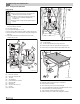


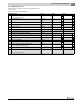

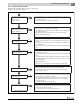

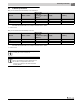

Table Of Contents
- Contents
- 1 Safety considerations
- 1.1 Key to symbols
- 1.2 Safety instructions
- 2 Product Description
- 3 Dimensions and Connections
- 4 Scope of delivery
- 5 Moving the boiler
- 6 Placing the boiler
- 7 Boiler installation
- 8 Check openings for combustion air supply and venting
- 9 Requirements for connection to chimneys or venting systems
- 10 Flue pipe installation
- 11 Placing the heating system in operation
- 12 Final start-up procedures
- 13 Start-up protocol
- 14 Taking the heating system out of operation
- 15 Boiler inspection and maintenance
- 15.1 Why is regular maintenance important?
- 15.2 Testing the flue system, including combustion air, air inlets and Ventilation openings
- 15.3 Inspection of the boiler and burner
- 15.4 Preparing boiler for cleaning
- 15.5 Cleaning the boiler
- 15.6 Cleaning the burner
- 15.7 Maintenance protocol
- 15.8 Troubleshooting the GC 144 II
- 16 Technical specifications
- 17 Electrical circuit diagrams

15
Boiler inspection and maintenance
Logano GC 144 II – 6 720 808 893 (2014/04)22
15.5.1 Cleaning the boiler with brushes
Burner removal
▶ Before opening a unit: disconnect electrical power and lock to
prevent accidental reactivation.
▶ Close main gas shut-off.
▶ Secure gas manifold with wire or cord.
▶ Remove igniter cable from ignition module ( figure 34, page 22).
▶ Disconnect cable connector from bottom of gas valve ( figure 34,
page 22).
▶ Label cables to the flame roll-out switch, then remove cable
( figure 34, page 22).
Fig. 34 Front view GC 144 II
[1] Flame roll-out switch
[2] Flame roll-out switch cable
[3] Gas valve
[4] Gas supply pipe
[5] Boiler temperature controller
[6] Ignition module
[7] Igniter cable
[8] Gas valve cable connector
[9] Pilot line
[10] Igniter cable
Fig. 35 Removing burner
[1] Screw nuts (two)
[2] Screws on gas manifold on top of gas valve (four)
▶ Remove four (4) screws from gas manifold on top of gas valve.
▶ Remove two (2) screw nuts on burner tray and take out the tray.
Fig. 36 Remove top cover
▶ Remove 4 screws on sides of the top cover and lift off.
▶ Remove top boiler insulation.
▶ Unscrew cleaning cover from the venting manifold.
▶ Cover control with foil to prevent entry of metal dust into the control.
▶ Use boiler brush to clean out flue gas passages.
▶ Clean combustion chamber and bottom insulation.
▶ Replace cleaning cover, install screws, and replace insulation.
WARNING: Risk to life from electric shock.
▶ Before opening a unit: disconnect electrical power
and lock to prevent accidental reactivation.
▶ If cables are connected incorrectly the system may
not operate correctly with possibly dangerous
consequences.
▶ After maintenance test the heating system for proper
function.
8
9
10
1
2
5
6
7
3
6 720 804 440-45.1T
4
2
6 720 804 440-46.1T
1
6 720 804 440-47.2T