
Install Instructions

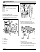


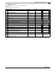


Table Of Contents
- Contents
- 1 Safety considerations
- 1.1 Key to symbols
- 1.2 Safety instructions
- 2 Product Description
- 3 Dimensions and Connections
- 4 Scope of delivery
- 5 Moving the boiler
- 6 Placing the boiler
- 7 Boiler installation
- 8 Check openings for combustion air supply and venting
- 9 Requirements for connection to chimneys or venting systems
- 10 Flue pipe installation
- 11 Placing the heating system in operation
- 12 Final start-up procedures
- 13 Start-up protocol
- 14 Taking the heating system out of operation
- 15 Boiler inspection and maintenance
- 15.1 Why is regular maintenance important?
- 15.2 Testing the flue system, including combustion air, air inlets and Ventilation openings
- 15.3 Inspection of the boiler and burner
- 15.4 Preparing boiler for cleaning
- 15.5 Cleaning the boiler
- 15.6 Cleaning the burner
- 15.7 Maintenance protocol
- 15.8 Troubleshooting the GC 144 II
- 16 Technical specifications
- 17 Electrical circuit diagrams

15
Boiler inspection and maintenance
Logano GC 144 II – 6 720 808 893 (2014/04) 21
Fig. 30 Gas valve
[1] ON/OFF knob (shown in ON position)
15.5 Cleaning the boiler
The boiler can be cleaned with brushes and/or by wet cleaning. Cleaning
tools are available as accessories.
Inspecting the ignition burner
▶ Observe the ignition burner through the sight glas window
( figure 31).
Fig. 31 GC 144 II
[1] Sight glass
▶ The flame must rise over the sensor by ½" to 1-½".
▶ The pilot ignition gas pressure must be adjusted if the flame is too
small or too large.
Fig. 32 Correct ignition flame setting
[1] Flame rises ½" to 1-½" above sensor
[2] Ignition flame
▶ Remove the safety screw on the adjustment screw for the igniter
( figure 24, page 17).Turn the inner adjustment screw clockwise
to reduce the size of the ignition flame, and counterclockwise to
increase it.
▶ After completed adjustment replace the safety screw
( figure 24, page 17).
▶ If the flame is too small, the pilot orifice needs cleaning
( figure 39, page 23). If the igniter flame is acceptable, start
cleaning.
Fig. 33 Gas valve
[1] Safety screw on igniter adjustment screw
The adjustment screw is located behind a safety screw
on the gas valve ( figure 33).
1
6 720 804 440-38.1T
1
6 720 804 440-39.1T
Be careful not to damage the pilot orifice during
installation and cleaning.
2
1
6 720 804 440-40.1T
1
6 720 804 440-41.1T