
Install Instructions
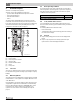

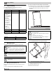
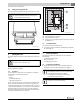


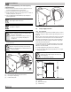
Table Of Contents
- Contents
- 1 Safety considerations
- 1.1 Key to symbols
- 1.2 Safety instructions
- 2 Product Description
- 3 Dimensions and Connections
- 4 Scope of delivery
- 5 Moving the boiler
- 6 Placing the boiler
- 7 Boiler installation
- 8 Check openings for combustion air supply and venting
- 9 Requirements for connection to chimneys or venting systems
- 10 Flue pipe installation
- 11 Placing the heating system in operation
- 12 Final start-up procedures
- 13 Start-up protocol
- 14 Taking the heating system out of operation
- 15 Boiler inspection and maintenance
- 15.1 Why is regular maintenance important?
- 15.2 Testing the flue system, including combustion air, air inlets and Ventilation openings
- 15.3 Inspection of the boiler and burner
- 15.4 Preparing boiler for cleaning
- 15.5 Cleaning the boiler
- 15.6 Cleaning the burner
- 15.7 Maintenance protocol
- 15.8 Troubleshooting the GC 144 II
- 16 Technical specifications
- 17 Electrical circuit diagrams

7
Boiler installation
Logano GC 144 II – 6 720 808 893 (2014/04)10
Description of field installed wiring connections using factory
supplied junction box.
▶ Remove two knock-outs from the left side of boiler panel to route
electrical feed and pump power into junction box.
▶ Route electrical power from the outside into junction box.
▶ Install a metal strain relief for the incoming power line on outside of
left boiler jacket panel. ( figure 12).
▶ Just use supplied wiring nuts and double proper wiring before
powering up the boiler.
▶ Check that the heating system functions correctly after any
maintenance work.
Fig. 11 Electrical junction box
[1] Electrical junction box (Inside of jacket cabinet)
[2] Incoming line voltage wiring
[3] Furnished wiring nuts.
Fig. 12 Strain relief for shielded electrical wiring
7.4 Fuel gas supply connection
7.4.1 Gas connections
For the gas pipe diameter required for the installation please see table 6
and table 7 ( page 11). Make sure that the pipe fitting has the correct
thread size.
Make sure that a sediment trap is installed at the inlet for the gas supply
pipe to the boiler. A manual stop valve must be installed outside the
boiler jacket if required by the local code. We recommend installing a
manual shut-off valve in the main gas pipe to the boiler. The gas pipe
must be fastened outside the boiler.
The local codes must be observed during installation of the gas piping
connections, otherwise the regulations of the National Fuel Gas Code,
ANSI Z 223.1 must be followed.
▶ Install gas piping without any undue stress on the piping.
▶ The Commonwealth of Massachusettes prohibits the use of copper
tubing for the gas line.
Fig. 13 Gas piping connection to gas valve – right or left side
[1] Gas feed
[2] Manual shut-off valve
[3] Sediment trap
When making the electrical connections use only wires
that are approved for electrical use.
Refer to the wiring diagrams for electrical details
( chapter 17, page 30) .
WARNING: Risk to life from electrical shock.
▶ When conducting maintenance work label all cables
before disconnecting them.
▶ If cables are connected incorrectly the system may
not operate correctly with possibly dangerous
consequences.
WARNING: Fire danger.
Hot boiler components may damage electrical wiring.
▶ Make sure that all cables are routed in the ducts or on
the boiler insulation.
3
1
6 720 804 440-11.2T
2
WARNING: Danger of explosion.
Leakage from the gas pipes and gas connections may
cause an explosion.
▶ Use soap solution to find leaks.
6 720 804 440-12.2T
6 720 804 440-13.2T
1
3
2