
User Guide


Boiler installation 8
41
We reserve the right to make any changes due to technical modifications.
Installation and maintenance instructions Logano G215 US oil/gas-fired boilers • Issue 2014/10
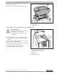
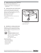
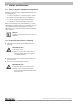
z Remove the Logamatic control panel cover. First
remove the cover screws.
z Secure the control panel with self-tapping screws.
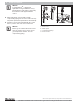
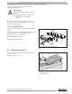
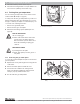
8.8.2 Installation of the temperature sensor set and burner cable
z Route capillary tubes and sensor wiring through the
cable opening of the front boiler jacket and connect
to test port.
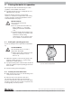
z Roll up surplus capillary tubes and sensor lead and
lay them on the thermal insulation.
z Route the burner cable through the cable entry in the
front boiler cover to the control panel.
z Connect the burner cable to the control in
accordance with the terminal markings.
Fig. 53 Removing the cover
1 Cover screws
2 Self-tapping screws
1
2
Fig. 54 Routing and connecting cables
1 Cable entry in the front boiler cover
2 Capillary tubes and sensor cable
3 Burner cable
4 Cable entry
5 Sensor well (test port)
1
3
5
2
4
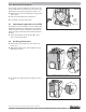
CAUTION!
SYSTEM DAMAGE
Capillary tubes may become unsound due
to severe kinking or sharp burrs.
z Carefully route capillary tubes using
large radius.