
Installation Manual


12
Circuit diagrams
Logano G115 WS US/CA – 6 720 813 418 (2014/10) 57
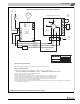
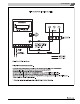
Fig. 55 Circuit diagram 8
II
Z
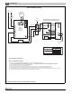
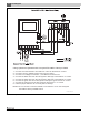
Using Hydrolevel Hydrostat
1. Connect room thermostat or end switch to T and TV terminals on control.
2. Connect incoming 120VAC power source to the control.
3. Connect Line Voltage to terminal L1, and Neutral to terminal L2.
4. Connect the black wire from the Carlin 60200 to terminal B1 on control.
5. Connect the white wire from the Carlin 60200 to terminal B2 on control.
6. Connect the green wire from Carlin 60200 to ground screw on control.
7. Install a jumper between TT on Carlin 60200.
8. The pink wire from the Carlin “in-line heater” may be connected to the
red/white wire in the Carlin 60200 control.
6 720 813 418-04.1T