
Installation Guide
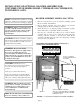


Page 9
Maintain adequate clearances for
accessibility for the purpose of
servicing and proper operation.
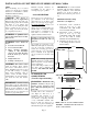
GAS CONNECTION
Check gas type. Use only the type of
gas indicated on the valve rating
plate. If the type of gas listed on the
plate is not your type of gas supply,
DO NOT INSTALL. Contact your
dealer for proper model.
Always use an external regulator for
all LP heaters to reduce the supply
tank pressure to a maximum of 13"
W.C. This is in addition to the
regulator furnished with the heater.
Warning: Connection directly to an
unregulated LP tank can cause an
explosion.
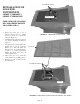
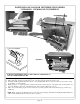
The normal gas connection is 3/8"
NPT made at the right rear side facing
stove. If a left side connection is
desired, the connecting pipe may be
routed under the rear of the burner
base to terminate at the right hand
side for connection to the inlet of the
valve.
NOTE: The connecting pipe must be
internally treated for protection from
sulfur compounds if copper tubing is
used for natural gas.
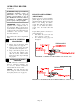
Test for leaks using a solution of soap
and water after completing the
connection. DO NOT USE OPEN
FLAME.
CLEARANCES TO
COMBUSTIBLES
(Vent-Free Operation Only)
WARNING: Maintain the
minimum clearances. If you can,
provide greater clearances from
floor, ceiling and adjoining side and
back walls.
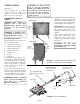
Carefully follow these instructions.
(See Figure 6). This stove is a
freestanding unit designed to set
directly on the floor. Do not place
stove directly on carpeting, vinyl tile
or any combustible material other
than wood. The stove must set on a
metal or wood panel extending the
full width and depth of the appliance.
IMPORTANT: You must maintain
minimum wall and ceiling clearances
during installation. The minimum
clearances are shown in Figure 6.
Measure from outermost point of stove
top.
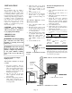
Minimum Wall and Ceiling
Clearances (See Figure 6)
A. Clearances from outermost
point of stove top to any
combustible side wall should
not be less than 4 inches.
B. Clearances from outermost
point of stove top to any
combustible back wall should
not be less than 4 inches
(Includes Corner Installations).
C. Clearances from the stove top
to the ceiling should not be less
than 48 inches.
NOTE:
Place freestanding stove in desired
position in room. Be sure to maintain
clearances to combustibles as outlined
in Minimum Wall and Ceiling
Clearances on this page.
*NOTICE: This heater is
intended for use as supplemental
heat. Use this heater along with your
primary heating system. Do not install
this heater as your primary heat
source. Do not run ceiling fan while
heater is running. In the event of a
power outage, you can use this heater
as your primary heat source.
WARNING: A qualified service
person must install heater. Follow
all local codes.
WARNING: Never install the
heater
in a bedroom or bathroom
in a recreational vehicle
where curtains, furniture,
clothing or other flammable
objects are less than 48 inches
from the front, top or sides of
the heater
in high traffic areas
in windy or drafty areas
CAUTION: This heater creates
warm air currents. These currents
move heat to wall surfaces next to
heater. Installing heater next to vinyl
or cloth wall coverings or operating
heater where impurities (such as
tobacco smoke, aromatic candles,
cleaning fluids, oil or kerosene lamps,
etc.) in the air exist, may discolor
walls.
IMPORTANT: Vent-free heaters
add moisture to the air. Although this
is beneficial, installing heater in rooms
without enough ventilation air may
cause mildew to form from too much
moisture. See Air for Combustion and
Ventilation, pages 4 through 5.
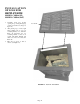
FIGURE 6 - MINIMUM CLEARANCES TO
WALLS AND CEILING
SIDE
WALL
FRONT VIEW
SIDE
WALL
CEILING
48" MINIMUM
INSTALLATION OF VENT FREE STOVE SERIES CFVB200, C100BA
NOTE: TYPICAL STOVE CABINET MODEL
BACK WALL
SIDE
WALL
4"
MINIMUM
TOP VIEW
4" MINIMUM
SIDE
WALL
4"
MINIMUM
WALL
WALL
4" MINIMUM
4" MINIMUM
CORNER VIEW