1593655 en Interface I100 Operation Manual
Imprint Product Identification: Operation Manual (Original) Interface I100 11593655 en Publication date: 12.2014, Version B BÜCHI Labortechnik AG Meierseggstrasse 40 Postfach CH9230 Flawil 1 EMail: quality@buchi.com BUCHI reserves the right to make changes to the manual as deemed necessary in the light of experi ence; especially in respect to structure, illustrations and technical detail. This manual is copyrighted.
BÜCHI Labortechnik AG Contents Contents 1 About this document........................................................................................................... 5 1.1 1.2 1.3 1.4 Warning notices in this document........................................................................................................ Symbols ............................................................................................................................................... 1.2.1 Warning symbols ........
Contents BÜCHI Labortechnik AG 6 Operation............................................................................................................................ 22 6.1 6.2 Function buttons ................................................................................................................................ Performing distillation ........................................................................................................................ 6.2.1 Manual mode ....................
BÜCHI Labortechnik AG 1 About this document | 1 About this document These operating instructions describe the Interface I100 at the time supplied. They are an integral part of the product and contain important information that is necessary for safe operation and maintenance. These operating instructions apply to all variants of the Interface I100 and are in tended primarily for laboratory staff.
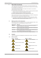
1 | About this document BÜCHI Labortechnik AG Symbol 1.2.2 Symbol Meaning Hot surface Healthharming or irritant substances Risk of hand injury Strong magnetism Mandatory directive symbols Symbol 1.2.3 Meaning Meaning Symbol Meaning Wear safety goggles Wear protective clothing Wear protective gloves Heavy load, do not lift without assistance Other symbols NOTE This symbol draws attention to useful and important information.
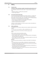
BÜCHI Labortechnik AG Safety | 2 2 Safety 2.1 Intended use The Interface I100 is intended for regulating and indicating vacuum within an operat ing range of 0 mbar to atmospheric pressure. It has been designed and built as an item of laboratory equipment and can be used in conjunction with the following de vices: Distillation apparatus, especially rotary evaporators Vacuumdrying cabinets 2.2 Use other than that intended Use of any kind other than that described in the section Chapter 2.
2 | Safety BÜCHI Labortechnik AG BUCHI service technicians Service technicians authorized by BUCHI have attended special training courses and are authorized by BÜCHI Labortechnik AG to carry out special servicing and repair measures. 2.4 Residual risks The device has been developed and manufactured using the latest technological ad vances. Nevertheless, risks to persons, property or the environment can arise if the device is used incorrectly.
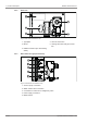
BÜCHI Labortechnik AG Product description | 3 3 Product description 3.1 Description of function The Interface I100 is designed for indicating, adjusting and controlling vacuum. It can regulate the Vacuum Pump V100 and the Recirculating Chiller F105 and thus con stantly maintain a set pressure. The pressure is measured capacitively and indicated as an absolute value. Measure ment is independent of the solvent used. 3.2 Configuration 3.2.1 Front view Fig.
3 | Product description 3.2.2 BÜCHI Labortechnik AG Rear view 1 4 2 3 5 Fig. 2: Rear view of Interface I100 1 Type plate 4 Vacuum connection 2 Mount 5 Venting valve with inert gas connec tion 3 RS485 connection (for recirculating chiller) 3.2.3 Side view from right (connections) 1 2 1 3 1 4 1 5 1 Fig.
BÜCHI Labortechnik AG 3.2.4 Product description | 3 Screen 1 4 1 5 1 6 1 7 1 2 1 8 1 3 1 Fig. 4: Screen layout 1 Operating mode 4 Specified pressure in system 2 Actual pressure in system 5 Analogue pressure indication 3 Functions of the buttons below 6 Vacuum valve connected 7 Recirculating chiller connected 8 Unit of pressure NOTE Depending on application, the standard display may show different symbols.
3 | Product description 3.2.5 BÜCHI Labortechnik AG Typical application The Interface I100 is designed to be used in the following combination of devices: Recirculating Chiller F-100 Fig. 5: Configuration of a complete system 1 Recirculating Chiller F100/F105 2 Rotavapor R100 3 Vacuum Pump V100 with Interface I100 The F100 and F105 are sealedsystem recirculating chillers. They are available in various capacity ratings. The F105 can be electronically controlled.
BÜCHI Labortechnik AG 3.2.6 Product description | 3 Type plate The type plate is on the rear of the Interface I100. BÜCHI Labortechnik AG CH-9230 Flawil/Switzerland Type: I-100 SN: 1000000000 Volt: 100 – 240 VAC Frequ.: 50/60 Hz Power: 10 W Built: 2014 Made in Switzerland 1 2 3 4 5 6 7 8 9 11 10 Fig.
3 | Product description BÜCHI Labortechnik AG 3.4 Technical data 3.4.1 Interface I100 3.4.2 3.4.3 Dimensions (W x H x D) 160 x 105 x 120 mm Weight 700 g Voltage 30 V DC Power consumption 10 W Solenoid valve power supply 24 V Measurement range 1400 – 0 mbar Regulating range 1100 – 0 mbar Measurement accuracy ± 2 mbar (after calibration at constant temperature) Temperature compensa tion 0.
BÜCHI Labortechnik AG Transport and storage | 4 4 Transport and storage 4.1 Transport IMPORTANT Risk of breakage due to incorrect transportation u Make sure that all parts of the device are safely packed in such a way as to pre vent breakage, ideally in the original box. u Avoid sharp movements during transit. u After transportation, check the device for damage. u Damage that has occurred in transit should be reported to the carrier. u Keep packing for future transportation. 4.
5 | Installation BÜCHI Labortechnik AG 5 Installation 5.1 Assembly The Interface I100 can be mounted either on the Vacuum Pump V100 or a laboratory stand. 5.1.1 Fitting an interface unit to the Vacuum Pump V100 Fitting the holder 1 2 4 3 Fig. 7: Fitting the holder for the Interface I100 1 Screw 3 Rubber plug (in thread for screw) 2 Holder for Interface I100 4 Lower hinge of holder The Torx key required for fitting the holder is included in the specifications supplied.
BÜCHI Labortechnik AG Installation | 5 Fitting the interface unit 1 2 3 Fig. 8: Fitting the Interface I100 1 Interface I100 3 Tscrew 2 Holder u Fit the interface unit (1) onto the holder (2). u Tighten the Tscrew (3) on the back of the interface unit by turning it clockwise. 5.1.2 Mounting interface unit on laboratory stand u Slide the interface unit onto the laboratory stand and fix it in place by tightening the knob on the back.
5 | Installation BÜCHI Labortechnik AG 5.2 Connections 1 2 5 3 4 6 1 7 1 Fig. 9: Connections on I100 u Connect the communication cable from the vacuum pump to the connection marked AS/SB (1). u Connect the lead from the coolant water valve to the RS485 socket (6) on the rear u u u u 5.3 panel, if used. Connect the communication cable from the valve unit to the connection marked VALVE (3), if used. Connect the lead from the power adapter to the 30VDC socket (4).
BÜCHI Labortechnik AG 5.4 Installation | 5 Basic settings Fig. 10: Menu u To change the basic settings, press the following buttons: Menu > Down arrow un til Settings is selected > Right arrow. u Use the arrow buttons to select whether the interface (controller) or system settings are to be changed.
5 | Installation BÜCHI Labortechnik AG 5.4.1 Controller settings The following settings can be adjusted: Fig. 11: Menu > Settings > Controller settings 20/42 Language The following languages can be selected: English, German, French, Italian, Spanish, Portuguese, Japanese, Chinese, Russian Aeration On: the system is automatically vented when the STOP button is pressed or when distillation automatically stops. Off: when the STOP button is pressed the current pressure is maintained.
BÜCHI Labortechnik AG 5.4.2 Installation | 5 System configuration The following settings can be adjusted: Fig. 12: Menu > Settings > System configuration Coolant valve Here you can specify whether a coolant water valve is connected. Max Pressure Here you can set the maximum pressure for the system, i.e. the pressure that is not to be exceeded in the system. If this pressure is reached, the venting valve opens.
6 | Operation BÜCHI Labortechnik AG 6 Operation 6.1 Function buttons The function of the four buttons underneath the screen varies according to application.
BÜCHI Labortechnik AG 6.2 Operation | 6 Performing distillation u Switch on the I100 at the master switch on the right. Depending on the requirements, the Interface I100 may be operated in any of the fol lowing modes: Continuous mode (see Chapter 6.2.2 "Continuous mode", page 24) Manual mode (see Chapter 6.2.1 "Manual mode", page 23) Timer mode (see Chapter 6.2.3 "Timer mode", page 25) 6.2.1 Manual mode u Press the Set button. 1 2 1 Fig.
6 | Operation BÜCHI Labortechnik AG 1 2 1 Fig. 14: Display during evacuation sequence u To increase the specified pressure while evacuation is in progress, press the P↑ button (2). The system pressure is increased by a small amount and the pump switches to Hold mode. The current pressure is maintained even if the specified setting has not yet been reached. u To cancel Hold mode, press the H Off button (1). The specified pressure previously set is reinstated.
BÜCHI Labortechnik AG 6.2.3 Operation | 6 Timer mode In Timer mode the set pressure is maintained for the set time. Depending on the vent ing setting (see Chapter 5.4.1 "Controller settings", page 20), the system is then either immediately vented or a message simply displayed indicating that distillation has fin ished. u Press the Menu button and for Mode select Timer. Fig. 15: Main menu u Press the Prog. button.
6 | Operation BÜCHI Labortechnik AG 6.3 Calibrating the pressure sensor The pressure sensor is calibrated at the factory by BUCHI prior to delivery. However, it can be recalibrated with the aid of an external reference pressure gauge at any time. u Press the Menu button and select Pressure sensor calibration. Fig. 16: Menu > Pressure sensor calibration 6.3.
BÜCHI Labortechnik AG 6.3.2 Operation | 6 Simple calibration (without temperature compensation) This calibration method is used to adjust the linearity of the pressure sensor at specific predefined pressure levels. During the calibration sequence the pressure sensor is calibrated at room temperature in six stages at normal atmospheric pressure and at 800, 600, 400, 200 and 10 mbar. NOTE This calibration process may only be carried out by authorized service technicians.
6 | Operation BÜCHI Labortechnik AG 6.3.3 Complete calibration (with temperature compensation) This calibration method is used to adjust the linearity of the pressure sensor at specific predefined pressure levels and temperatures. During the calibration sequence the pressure sensor is calibrated at room temperature and at a temperature of approx. 55 °C in six stages at normal atmospheric pressure and at 800, 600, 400, 200 and 10 mbar.
BÜCHI Labortechnik AG 6.3.4 Operation | 6 Loading the factory calibration This functions enables you to reset the calibration to the factory settings as supplied. Any previously saved calibration settings will be deleted. u To reset the calibration to the factory settings as supplied, open the calibration menu and select the option Load factory calibration. The device asks you to confirm that the factory calibration should be reloaded.
7 | Cleaning and servicing 7 BÜCHI Labortechnik AG Cleaning and servicing NOTE Users may only carry out the servicing and cleaning operations described in this sec tion. Any servicing and repair work which involves opening up the housing may only be carried out by BUCHI service technicians. u Use only genuine BUCHI consumables and spare parts in order to ensure correct operation of the device and preserve the warranty. 7.
BÜCHI Labortechnik AG Help with faults | 8 8 Help with faults 8.1 Faults, possible causes and remedies Fault Possible cause Remedy Device does not work Device is not connected to power supply u Check power supply (see Valve or pump frequently switches over System leaking u Check system for leaks (see Chapter 5.2 "Connections", page 18). Rotavapor operating instruc tions). u If necessary, replace tubing and/or seals.
8 | Help with faults 8.2 BÜCHI Labortechnik AG Error messages Error message Remedy Pressure sensor is defective. u Contact BUCHI Customer Service. Pressure sensor not calibrated. u Calibrate pressure sensor (see Chap ter 6.3 "Calibrating the pressure sen sor", page 26). Data transmission error on RS485. u Check RS485 lead and make sure that it is only connecting an interface unit to a recirculating chiller. Excess pressure in system.
BÜCHI Labortechnik AG Taking out of service and disposal | 9 9 Taking out of service and disposal 9.1 Taking out of service u Switch off the Interface I100 and disconnect it from the mains power supply. u Remove all tubing and communication cables from the device. 9.2 Disposal The operator is responsible for proper disposal of the Interface. u When disposing of equipment observe the local regulations and statutory require ments regarding waste disposal.
10 | Appendix BÜCHI Labortechnik AG 10 Appendix 10.1 Solvent table Solvent Formula Molar Evaporation en Boiling mass in g/ ergy in J/g point in °C mol at 1013 mbar Density in Vacuum in g/cm3 mbar for 40 °C boiling point Acetone CH3H6O 58.1 553 56 0.790 556 nAmyl alcohol, npentanol C5H12O 88.1 595 37 0.814 11 Benzene C 6H 6 78.1 548 80 0.877 236 nbutanol C4H10O 74.1 620 118 0.810 25 Tert butyl alcohol (2 C4H10O methyl2propanol) 74.1 590 82 0.
BÜCHI Labortechnik AG Appendix | 10 Solvent Formula Molar Evaporation en Boiling mass in g/ ergy in J/g point in °C mol at 1013 mbar Density in Vacuum in g/cm3 mbar for 40 °C boiling point 1,1,2,2tetra chloroethane C2H2Cl4 167.9 247 146 1.595 20 Carbon tetrachloride CCl4 153.8 226 77 1.594 271 1,1,1trichloroethane C2H3Cl3 133.4 251 74 1.339 300 Tetrachloroethylene C2Cl4 165.8 234 121 1.623 53 THF (tetrahydrofu rane) C 4H 8O 72.1 – 67 0.
10 | Appendix BÜCHI Labortechnik AG 10.2 Spare parts and accessories u Use only genuine BUCHI consumables and spare parts in order to ensure correct, safe and reliable operation of the system. NOTE Any modifications of spare parts or assemblies are only allowed with the prior written permission of BUCHI. 10.2.1 Accessories Communication cable MiniDIN, 0.
BÜCHI Labortechnik AG Appendix | 10 Woulff bottle. 3neck, 800mL, P+G For trapping particles and droplets and for pressure equalization 10.2.2 025519 Wear parts Seals For cap nut, GL14, FEP 038225 Hose barbs Set. 2pcs, bent (1), straight (1), GL14, silicone seal Content: Hose barbs, cap nuts, seals 041939 Set. 4pcs, bent, GL14, silicone seal, incl. cap nut Content: Hose barbs, cap nuts, seals 037287 Set.
10 | Appendix BÜCHI Labortechnik AG 10.3 10.
BÜCHI Labortechnik AG 10.
10 | Appendix BÜCHI Labortechnik AG 10.6 FCC requirements (for USA and Canada) English: This equipment has been tested and found to comply with the limits for a Class A digi tal device, pursuant to both Part 15 of the FCC Rules and the radio interference regu lations of the Canadian Department of Communications. These limits are designed to provide reasonable protection against harmful interference when the equipment is op erated in a commercial environment.
www.buchi.