
Instruction Manual


5 Putting into operation
45 B-290 Operation Manual, Version I
5
1
3
2
4
4
5
1
4
4
6
7
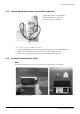
• Apply the tubes b to h according to the
above figures. For the tubes d and e, apply
cable binders to fixate them at their connec-
tion.
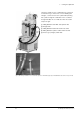
• Install the spray gas tube to the capillary inlet
connector on top of the heating bath.
• Connect the gas flow tube from the capillary
outlet to the nozzle inlet (gas).
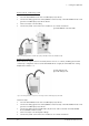
• The feeding tube is connectable in two ways
depending on whether the nozzle cleaning
option is required or not.
• The heating liquid tubes are connected from
the bath to the nozzle port (C in) and from
the nozzle port (C out) throught the pump
back to the bath.
• This way, the nozzle is also heated to prevent
any solidification and blocking.
• Adjust the peristaltic pump bed to the 6 mm
silicone tube.
a Needle valve for dosage
b Feeding tube with nozzle cleaning option: Needle
valve - nozzle (feed)
c Cleaning gas nozzle: Instrument - nozzle (top)
d Heating liquid tube: Bath - nozzle (C in) -
nozzle (C out) - peristaltic pump - bath
e Drain tube for heating liquid
f Gas flow tube: Instrument - capillary inlet
g Gas flow tube: Capillary outlet - nozzle (gas)
h Feeding tube without nozzle cleaning option
i Nozzle cleaning unit
j Screw connection for feeding tube
k Closed feed connection
Fig. 5.26: Installing the spray chilling tubing with (left) or without nozzle cleaning option (right)
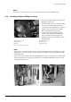
5.15 Installation check
Carry out an installation check after a successful installation and prior to the first spray drying
process.
• Inspect the glass visually for possible damage.
• Check the electrical connections.
• Make sure that the cover of the product collection vessel is connected to the instrument by means
of the cable for arresting electrostatic charges.
• Make sure that the outlet temperature probe is inserted in the coupling.