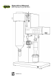
Operation Manual Mini Spray Dryer B-290 093001 en
Table of contents Table of contents 1 2 3 4 5 About this manual . . . . . . . . . . . . . . . . . . . . . . . . . . . . . . . . . . . . . . . 6 Safety . . . . . . . . . . . . . . . . . . . . . . . . . . . . . . . . . . . . . . . . . . . . . . 7 2.1 User qualification . . . . . . . . . . . . . . . . . . . . . . . . . . . . . . . . . . . . 7 2.2 Proper use . . . . . . . . . .
Table of contents 6 7 8 9 10 5.11 Installing the Inert Loop B-295 . . . . . . . . . . . . . . . . . . . . . . . . . . . . .39 5.12 Dehumidifier B-296 and Inert Loop B-295 combination . . . . . . . . . . . . . . . . .42 5.13 Installing the Dehumidifier B-296 . . . . . . . . . . . . . . . . . . . . . . . . . . . .42 5.14 Installing the Spray Chilling Accessory . . . . . . . . . . . . . . . . . . . . . . . .
Table of contents 11 10.12 Decontamination Glass-Set and sterile filter . . . . . . . . . . . . . . . . . . . . . . .77 10.13 Acid resistant accessories . . . . . . . . . . . . . . . . . . . . . . . . . . . . . . . 78 Declarations and requirements . . . . . . . . . . . . . . . . . . . . . . . . . . . . . . . 79 11.1 FCC requirements (for USA and Canada) . . . . . . . . . . . . . . . . . . . . . . . .
1 1 About this manual About this manual This manual describes the Mini Spray Dryer B-290 and its optional accessories and provides all information required for its safe operation and to maintain it in good working order. It is addressed to laboratory personnel and operators in particular. Read this manual carefully before installing and running your system and note the safety precautions in chapter 2 in particular.
2 2 Safety Safety This chapter highlights out the safety concept of the instrument and contains general rules of behavior and warnings from direct and indirect hazards concerning the use of the product. For the users safety, all safety instructions and safety messages in the individual sections shall be strictly observed and followed. Therefore, the manual must always be available to all persons performing any tasks described herein. 2.
2 2.3 Safety Improper use Applications not mentioned in section 2.2 are considered to be improper. Also, applications which do not comply with the technical data (see section 3 of this manual) are considered to be improper. The operator bears the sole risk for any damages or hazards caused by such improper use. The following uses are expressly forbidden: • • • • • Use of gases with unknown chemical composition. Spray drying of biohazardous materials such as viruses or bacteria.
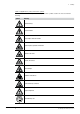
2 Safety Table of supplementary safety information symbols The reference list below incorporates all safety information symbols used in this manual and their meaning.
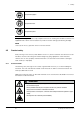
2 Safety Wear protective goggles Wear protective mask Wear protective gloves Additional user information Paragraphs starting with NOTE transport helpful information for working with the device/software or its supplementaries. NOTEs are not related to any kind of hazard or damage (see following example). NOTE Useful tips for the easy operation of the instrument/software. 2.5 Product safety Safety warnings in this manual (as described in section 2.
2 ! Safety DANGER Death or serious poisoning by gases or particles due to O2- sensonr or filter malfunction • • • • • Exchange defective O2-sensor immediately Exchange O2-sensor regularly within the specified maintenance intervals Exchange clogged filters immediately Exchange filters regularly within the specified maintenance intervals Dispose of filter immediately ! DANGER Death or serious poisoning by inhalation or incorporation of dried particles during spray process.
2 ! Safety DANGER Death or serious posioning by inhalation or incorporation of dried particles at recovery.
2 ! Safety WARNING Death or serious poisoning by contact or incorporation of harmful substances at use.
2 ! Safety NOTICE Risk of instrument damage by wrong mains supply. • • 2.5.2 External mains supply must meet the voltage given on the type plate Check for sufficient grounding Warning labels on housing and assemblies The following warning sticker(s) can be found on the housing or assemblies of the Mini Spray Dryer B-290 and Inert Loop B-295: Symbol Meaning Location Do not touch Label, located at the spray cylinder, hot item, hot B-290 surface! 2.5.
2 ! Safety WARNING Serious chemical burns by corrosives. • • • • • • • 2.5.4 Observe all data sheets of the used chemicals Handle corrosives in well ventilated environments only Always wear protective goggles Always wear protective gloves Always wear protective clothes Do not use damaged glassware Wear protective mask when working with inhalable particles Safety elements and measures To arrest electrostatic charges from the instrument, it is internally grounded.
2 Safety Glass • Use of inert 3.3 borosilicate glass. • Grounded coating of the inner surface of the cyclone to prevent any electrostatic charge of the power. • Screw couplings between glass connections to prevent glass breakage. Optional system configuration with Inert Loop B-295 • Overpressure leakage detection. • Safe gas condition (< 6 % O2 content) is detected and enables the regulation of the drying gas mixture via a communication cable. 2.
3 3 Technical data Technical data This chapter introduces the reader to the instrument specifications. It contains the scope of delivery, technical data, requirements and performance data. 3.
3 3.1.2 Technical data Standard accessories Table 3-2: Standard accessories Product Order number Operation Manual: 3.1.
3 Technical data Table 3-4: Standard accessories with the B-290 Acid resistant (cont.) 3.1.5 Temperature sensor support adapter 11056318 Clamp ring ID 8 mm 11056387 O-ring FPM 8×1 mm 004221 Connecting nipple PFA coated 11056328 Connecting piece PFA coated 11056334 Needle 0.7 mm titanium 11056415 Nozzle tip 0.
3 3.2 Technical data Technical data overview Table 3-6: Technical data Mini Spray Dryer B-290 Power consumption max. 2900 W Connection voltage 200–230 V ± 10 % Frequency 50/60 Hz Environmental conditions Temperature Altitude Humidity for indoor use only 5–40 °C up to 2000 m maximum relative humidity 80 % for temperatures up to 31 °C decreasing linearly to 50 % relative humidity at 40 °C Evaporating capacity 1.0 l/h H2O, higher for organic solvents Airflow max.
3 Technical data Table 3-7: Technical data Spray Chilling accessory (cont.) Heating liquid water or a thermal oil (polyethylene glycol PEG 400 with low viscosity) Heating liquid volume 1.4 liter Max. melting point of sample 70 °C Table 3-8: Technical data Inert Loop B-295 Power consumption max. 1400 W Connection voltage 200-230 V ± 10 % Frequency 50/60 Hz Min. outlet temperature down to –25 °C Rate of cooling 800 W at –10 °C Dimensions (W×H×D) 60×70×84.
4 4 Description of function Description of function This chapter explains the basic working principle of the Mini Spray Dryer B-290 Basic (open mode only) and the Mini Spray Dryer B-290 Advanced (for closed mode operation). It also shows how the instruments are structured and provides a general functional description of the assemblies. 4.1 Functional principle of the drying gas The Mini Spray Dryer B-290 operates according to a co-current drying gas (e.g. air in open mode) and product stream.
4 Description of function The nozzle cap has an inserted ruby stone with a precise opening and sharp edges to guarantee a precise and reproducible spray cone. The smaller nozzle cap of 1.4 mm diameter leads to a lower consumption of spray gas, as the concentric ring around the nozzle is smaller. This nozzle is recommended when nitrogen is used to minimize operating costs. The larger nozzle cap opening of 1.
4 4.5 Description of function Dehumidifier B-296 Mini Spray Dryer B-290 Dehumidifier B-296 8 7 1 2 3 6 4 a Ambient air b Condensation c Cooling unit d Condensed water 5 e Product f Exhaust gas g Compressed air as spray gas h Feed Fig. 4.4: Open loop Mini Spray Dryer B-290 with Dehumidifier B-296 for inlet air conditioning Use as inlet air conditioning The Dehumidifier B-296 is an accessory to enable a drying under constant and reproducible humidity conditions cooling to a dew point of 3–5 °C.
4 4.6 Description of function Spray chilling accessory During spray chilling a hot melt is dispersed into a cold gas stream. The droplets are solidified into particles and are separated. The matrix substance and the active ingredients are heated above the melting point. Highest melting point is 70 °C. The nozzle is also heated to prevent any blocking. No additional thermostat is required, as the existing heating control and peristaltic pump in the instrument are used.
4 4.7.1 Description of function Feed switch valve and remote control panel Fig. 4.7: Feed switch valve and remote control panel The remote control panel enables an easy operation even within a closed fume hood. The flow meter for the spraying gas is the only parameter which cannot be adjusted via the remote control panel. The feed switch valve is a useful tool together with the remote control panel.
5 5 Putting into operation Putting into operation This chapter describes how the instrument is installed and gives instructions on initial startup. NOTE Inspect the instrument for damages during unpacking. If necessary, prepare a status report immediately to inform the postal company, railway company or transportation company. Keep the original packaging for future transportation. 5.1 Installation site Put the instrument on a stable, horizontal surface.
5 Putting into operation NOTE To cut the power in case of an emergency by unplugging, the instruments or any other items must not block the mains plug! External connections and extension lines must be provided with a grounded conductor lead (3-pole couplings, cord or plug equipment). All used power cords must meet the input power requirements. Demands on the mains circuit The mains circuit must • provide the voltage that is given on the type plate of the instrument.
5 5.4 Putting into operation Installing the glass assembly ! CAUTION Risk of minor or moderate cuts by sharp edges. • • Do not touch defective or broken glassware with bare hands Do not touch thin metal edges To install the spray cylinder, proceed as follows: 1 2 3 8 7 6 5 • S crew the seal holder b on the instrument using the three knurled screws. • Connect the separation flask d to the spray cylinder c by closing the screw connection (SVL 42) tightly.
5 Putting into operation • C onnect the outlet temperature sensor o to the plug in the housing. • Insert the outlet temperature sensor into the connection piece f and screw it in. A metallic ring and O-ring is inserted to seal the probe. • Close all connections tightly. 15 6 Fig. 5.2: Installing the glass assembly 5.5 Installing the spraying nozzle • I nsert the nozzle into the heater element at the top of the instrument.
5 5.6 Putting into operation Installing the filters Notice Risk of instrument damage by internal overpressure. • • • 5.6.1 External supply pressure must meet the system specifications Exchange clogged or defective filters immediately Dispose of clogged or defective filters immediately Inlet filter installation Use Pre-filtering of environmental air to keep most impurities and particles away from the spray drying process. Fig. 5.
5 Putting into operation • U nscrew all screw caps of the tubing at the filter head a and unhook the complete filter from the holder. • Unscrew the screw cap b and pull off the filter housing glass. Remove the sealing ring. a b c d filter housing glass filter cartridge Fig. 5.7: Outlet filter installation • Unscrew the hose clamp c and pull off the filter cartridge. • Remove the hose clamp d from the filter cartridge. ➡ Wash the polyester filter manually or in a laboratory washing machine.
5 5.6.3 Putting into operation PTFE filter membrane installation b c a filter tube Fig. 5.8: Outlet fi lter membrane (PTFE) installation • Pull out the end-cap a of the filter membrane. • Unscrew the hose clamp b and pull off the filter membrane. • Remove the hose clamp c from the filter tube. ➡ Gently flush the PTFE filter membrane manually only. Use standard soap detergents for cleaning. It is recommended to exchange the filter membrane regularly. For installation proceed in reverse order.
5 Putting into operation NOTE Make sure the end-cap properly seals the filter carrier and the filter membrane! This is essential for effective filtering. Fig. 5.9: Installing the end-cap to seal the filter tube Mind the correct mounting direction of the sealing ring (order no. 040471) at the filter housing glass! NOTE The flange screw coupling made of aluminum (order no.
5 Putting into operation Installation as safety outlet filter Install the filter between the outlet filter and the Aspirator. This will hold back finest particles from the Aspirator and the environment e.g. the laboratory air. Fig. 5.11: Cleaning filter installed with stop cock 5.7 Adjusting the peristaltic pump bed and choosing the feeding tube The pump bed of the peristaltic pump is adjusted ex works to the standard silicone tube. If different tubes, e.g.
5 Putting into operation a Tube to spraying nozzle b Handle, pump bed c Distilled water d Flow meter valve e Adjusting screw, pump bed Fig. 5.12: Pump bed adjustment 1. 2. 3. 4. 5. 6. Remove spraying nozzle from the Mini Sprayer B-290 and hold spraying nozzle into a suitable container. Insert tube a in to the pump bed. Put tube on the suction side into distilled water c. Close pump bed with handle b. Unscrew adjusting screw e 1 turn. Open the flow meter valve d to 40 mm.
5 5.8 Putting into operation Tubing installation The Mini Spray Dryer B-290 needs compressed gas for the two-fluid nozzle and the nozzle cleaner between 5 and 8 bar. Therefore, the air or nitrogen is connected on the rear of the instrument via a quick coupling. Fig. 5.13: Quick coupling rear side The Mini Spray Dryer B-290 can be used in an open or closed mode. The open mode is set in the suction mode as a standard.
5 Putting into operation a Exhaust tube of cyclone or filter, respectively b Tubing between aspirator and heater 2 1 Fig. 5.15: Open mode set-up in pressure mode 5.9 Installing the compressor Use For the spray process compressed air or gas is necessary. If no compressed air supply is available in the laboratory the compressor can be installed instead. Installation • Place it in a dry, dust free and well tempered room with appropriate ventilation.
5 5.10 Putting into operation Quick hose couplings Use For fast and reliable connecting/disconnecting of polypress tubes e.g. the tubing of Inert Loop B-295 and Dehumidifier B-296. Installation • C ut the polypress tube with a sharp knife or a special tube cutter into two halfs with a clean cut. The tube ends must be straight! • Slip one hose clamp over each tube end. • Use one male and one female coupling adapter and install them at the tube ends. • Secure the coupling adapters with the hose clamps.
5 ! Putting into operation Warning Death or serious poisoning by contact or incorporation of harmful substances at use. • • • • • • • Before operation, check the instrument for correct assembling Before operation, inspect sealings and tubes for good condition Exchange worn out or defective parts immediately Exchange clogged filters immediately Only operate the instrument in ventilated environments Directly withdraw released gases and gaseous substances by sufficient ventilatio.
5 Putting into operation The Inert Loop B-295 has a sideward hose connection for the exhaust gas. Due to the constant feeding with nitrogen, a certain amount of it is permanently leaving the system through this outlet tube. If air is sucked in through the tube, this is an indication that the closed loop is not tight.
5 5.12 Putting into operation Dehumidifier B-296 and Inert Loop B-295 combination a Mini Spray Dryer B-290 outlet tube b Dehumidifier B-296 outlet tube c Inert Loop B-295 outlet tube Fig. 5.21: Tube connections B-290, B-296 and B-295 • Connect the Mini Spray Dryer B-290 outlet tube a with the inlet of the Dehumidifier B-296 • Connect the Dehumidifier B-296 outlet tube b to the Inert Loop B-295 inlet. • Connect the outlet c of the Inert Loop B-295 to the Mini Spray Dryer B-290. 5.
5 Putting into operation Used as inlet air conditioning system Installation steps: 1. Place the Dehumidifier B-296 next to the Mini Spray Dryer B-290. 2. Connect the tubing a from the outlet (labelled on the enclosure) of the Dehumidifier B-296 to the gas inlet of the Mini Spray Dryer B-290 heater. 3. Use hose clamps to fix the tubing. 4. Connect the power cord to the mains. The device can now be switched on. a Dehumidifier B-296 outlet tube Fig. 5.
5 Putting into operation NOTE See section 7.6 for information about the cleaning procedure of the Dehumidifier B-296. 5.14 Installing the Spray Chilling Accessory 2 3 1 4 5 6 a Product feed vessel b Heating bath c Heater • M ount the complete bath b on the top of the Mini Spray Dryer B-290. • Use the knurled screws to fix the spray chilling accessory on the Mini Spray Dryer B-290 cover panel.
5 Putting into operation 1 1 5 2 5 3 4 4 4 6 7 a Needle valve for dosage b Feeding tube with nozzle cleaning option: Needle valve - nozzle (feed) c Cleaning gas nozzle: Instrument - nozzle (top) d Heating liquid tube: Bath - nozzle (C in) nozzle (C out) - peristaltic pump - bath e Drain tube for heating liquid 4 • A pply the tubes b to h according to the above figures. For the tubes d and e, apply cable binders to fixate them at their connection.
5 5.16 Putting into operation Additional cleaning measures for food, pharma and cosmetic applications For food, pharma and cosmetic products additional measures are required during the whole spray drying process to establish the necessary hygienic level. Any risk of infection, diseases or contagion must be excluded! To disinfect the Mini Spray Dryer B-290 in place the glass does not have to be sterilized separately.
6 6 Operation Operation This chapter gives examples of typical instrument applications and instructions on how to operate the instrument properly and safely. ! Danger Death or serious poisoning by inhalation or incorporation of dried particles during spray process.
6 6.1 Operation Layout of the operating and display elements a Main switch b Flow meter for spraying gas volume c Needle valve for gas flow adjustment 1 2 3 Fig. 6.1: Switch, flow meter and valve 3 4 5 6 1 2 a LED display current value inlet air temperature b LED display current value outlet air temperature c LED display set value inlet air temperature d LED display aspirator output in % of max. aspirator rate e LED display pump output in % of max.
6 6.2 Conversion tables for the parameters 6.2.1 Flow meter spraying air (rotameter) Operation The rotameter is an indicator for the spray gas flow. The table gives a correlation between indicated height and volume throughput. The nozzle has a certain pressure drop which increases with higher gas flow. As the gas volume strongly corresponds to the actual pressure, the table also contains a row for the effective volume flow, determined in a spray process with air.
6 6.2.3 Operation Aspirator The aspirator has a maximum gas flow rate of approx. 35 m3/h. The flow depends on the pressure drop of the overall system. To determine the exact volume flow for steady and reproducible operating conditions, a measurement tube is supplied as an accessory. A handheld gas flow meter (hot-wire flow meter) is required for the measurement. Fig. 6.4: Aspirator settings versus throughput 6.3 Spray process During the spray process some parts i.e.
6 6.4 Operation Optimizing parameters The parameters relevant for the spray process (aspirator and pump performance as well as inlet temperature) all correlate with and depend on each other. To give you an overview over the parameter settings best suited for your process, special training papers can be downloaded directly from the Internet. Please visit our homepage www.buchi.com. In the section Fields of Activities/Spray Drying, you will find the document to download. 6.
6 Operation If the system is run with a PTFE filter, the fine particles can partially be recovered by counter-pulsating the filter membrane and blowing the particles away. For this purpose, proceed as follows: Fig. 6.5: Recovering particles of the outlet filter • A ttach the PTFE membrane instead of the polyester filter and close the bottom with a polypropylene plug. • Separate the manometer tube from the filter and remove the filter housing completely from the holder.
6 6.7 Operation Operation with the Inert Loop B-295 ! Danger Death or serious poisoning by gases or particles due to O2– sensor or filter malfunction • • • • • Exchange defective O2– sensor immediately Exchange O2– sensor regularly within the specified maintenance intervals Exchange clogged filters immediately Exchange filters regularly within the specified maintenance intervals Dispose of filter immediately ! Danger Death by suffocation or serious poisoning by inhalation of inert gases.
6 2. 3. 4. 5. 6. 7. 8. 6.7.1 Operation Usually the Inert Loop is set on -20°C for optimal solvent recovery. Some solvents tend to freeze in the Inert Loop B-295, while working with those please adjust the set temperature to a higher one, use the buttons c and d. The display of the Inert Loop B-295 e shows the set temperature and the current temperature. Switch on the aspirator (see figure 6.2 on page 52). Check whether the spray gas source is an inert gas, normally nitrogen.
6 6.8 Operation Operation with the Spray Chilling Accessory To operate the Spray Chilling Accessory, proceed as follows: 1. 2. 3. 4. 5. 6. 7. 8. 9. 10. 11. 12. 13. 14. 15. 16. 17. 18. 19. 55 Fill a heating liquid, e.g. water or a thermal oil (polyethylene glycol PEG 400 with low viscosity) into the heating bath and check whether the tubings are connected correctly. For sample melting points below 50 °C, water can be used as heating liquid.
6 6.9 Operation Mini Spray Dryer B-290 acid resistant For basic operations please see chapters 6.1–6.7. Nozzle cleaning instructions 1. Clean the nozzle parts immediately after each spray drying run. 2. Wash the nozzle parts with a mild detergent solution. 3. Rinse the parts with hot water and let them dry. 4. Examine the nozzle parts under a microscope to verify that they are clean. 5. Check the integrity of the O-rings. Replace if necessary.
7 7 Maintenance and repairs Maintenance and repairs This chapter gives instructions on all maintenance work to be performed in order to keep the instrument in good working condition. ! Danger Death or serious poisoning by inhalation or incorporation of dried particles during maintenance.
7 ! Maintenance and repairs CAUTION Minor or moderate injuries by hot heating bath content. • • Do not drop any water into the hot heating liquid Wear safety goggles Notice Risk of instrument and instrument damage by liquids and detergents. • • • 7.1 Do not spill liquids over the instrument or parts of it Wipe off any liquids instantly Use ethanol or soapy water as detergent only Housing Check the housing for defects (switches, plugs) and clean it regularly with a damp cloth. 7.
7 7.4 Maintenance and repairs Aspirator cleaning The aspirator of the Mini Spray Dryers can be contaminated from particles, especially when no outlet filter is used. This is a description how to clean the aspirator efficiently and fast. Disconnect the “Polypress” tube from the glass assembly and heater respectively. Fig. 7.1: Disconnecting Polypress tube • Fill one vessel with water and prepare an empty canister with a small opening.
7 • • • • 7.6 Maintenance and repairs Provide a collection vessel to collect the cleaning medium flowing from the system. Open the drain valve and lower the exhaust tube, so that the cleaning medium flows out. Rinse out and dry the condensate vessel. Reinstall the condensate vessel. To dry the working circuit connect the Mini Spray Dryer B-290 and dry it by running the Aspirator with dry air.
7 7.8 Maintenance and repairs Replacing the oxygen sensor of the Inert Loop B-295 After approximately 2 years of operation the oxygen concentration displayed by the sensor decreases drastically. The sensor should now be replaced. For this purpose: • • • • • Open the front plate with an allen key. Disconnect the cable by turning the plug. Screw the sensor out and replace it by a new one. Reconnect the cable. Calibrate the sensor according to chapter 7.6, Calibrating the oxygen sensor. Fig. 7.
8 8 Troubleshooting Troubleshooting This chapter helps to resume operation after a minor problem has occurred with the instrument. It lists possible occurrences, their probable cause and suggests how to remedy the problem. The troubleshooting table below lists possible malfunctions and errors of the instrument. The operator is enabled to correct some of those problems or errors by him/herself. For this, appropriate corrective measures are listed in the column “Corrective measure”.
8 Troubleshooting Table 8-1: Error messages and their remedy (cont.) 8.
8 Troubleshooting Table 8-2: Malfunctions and their remedy (cont.
9 9 Shutdown, storage, transport and disposal Shutdown, storage, transport and disposal This chapter instructs how to shut down the instrument, how to pack it for storage or transport, and specifies the storage and shipping conditions. ! WARNING Death or serious poisoning by contact or incorporation of harmful substances. • • • • • • 9.
10 10 Spare parts Spare parts This section lists spare parts, accessories and options including their ordering information. Only order spare parts and consumables from BUCHI to maintain the warranty status and to assure best performance and reliability of the system and affected components. Any modifications to the spare parts used are only allowed with the prior written permission of the manufacturer.
10 Spare parts Table 10-2: Three fluid nozzle 044629 044628 Description Order number Three fluid nozzle, complete 046555 Three fluid nozzle conversion kit 046556 Screw connection product tube 044628 Screw connection air and cooling 044629 Inner nozzle tip (0.7 mm) 046554 Nozzle tip (2.0 mm) 046377 Nozzle cap (2.8 mm) 046375 Set of O-rings 044759 046556 046377 046554 046375 Table 10-3: Spray Nozzle ∅ 1.
10 Spare parts Table 10-6: Standard O-rings FKM, for all standard to medium-aggressive applications 038348 Description Order number O-ring for nozzle, FKM (green), 2× 044645 O-ring nozzle cap silicone (red), 2× 002103 O-ring for needle and nozzle tip, FKM (green), 4× 004222 O-ring for nozzle cleaner, FKM (black), 2× 038348 Set of standard O-rings, complete 044759 21.0×2.0 mm 004222 044645 16.0×2.0 mm 6.0×1.5 mm 004222 002103 3.0×1.
10 Spare parts Table 10-7: Highly resistant O-rings FFKM, for all medium to aggressive applications Description Order number O-ring for screw coupling, 046363 FFKM (black), 2× 044469 37.69×3.5 mm 046361 (044645) O-ring for nozzle tip, FFKM (green), 2× 046361 O-ring for nozzle cleaner, FKM (black), 2× 044469 Set of FFKM O-rings, complete 046364 6.0×1.5 mm 3.0×1.5 mm 046361 (002103) Set, complete 046363 NOTE O-rings in brackets are part of the standard O-ring set, order no.
10 10.2 Spare parts Glass parts Table 10-8: Glass parts 1 046311 044726 (brown glass) 044673 044710 044711 044712 046333 046334 (b.g.) 040162 003551 040674 004189 004348 (b.g.) 004192 034139 040471 044678 003551 040674 004188 004343 (b.g.) 044678 044727 (b.g.
10 040133 Table 10-10: Glass parts 2 046343 046371 044681 032017 046363 Description Order number O-ring FKM for screw coupling 001535 Tension spring 032017 Set flange screw coupling (2 units) 040133 Set O-ring and clamping ring (5 units) 046343 O-ring FFKM for screw coupling 046363 Coupling flange 044681 O-ring for temperature sensor 5.0×2.5 FFKM 046371 001535 046368 11056879 b.g. 11056751 003223, 003561 or 005203 046367 11056878 b.g.
10 10.
10 Spare parts Table 10-16: Tubing (cont.) Description 11056479 (Sealing) Order number Tygon tube MH 2075 transparent (per m) 046314 Tygon tube F 4040 A yellow (per m) 046315 Screw cap SVL 42 003551 Connecting piece for polypress tube 044679 Hose clamp 25–40 mm 004236 Quick hose coupling 045656 Sealing FKM for hose coupling 11056479 045656 10.5 Trolley The trolley consists of powder-coated stainless steel. Dimensions (L×W×H): 850×420×560 mm Table 10-17: Trolley 10.
10 10.7 Spare parts Feed switch valve For safe and automated switching between pure solvent and product when starting and ending the spray drying process. 044725 046304 Table 10-19: Feed switch valve Description Order number Feed switch valve 044725 Y-piece connector 046304 Metal tube connector 004251 004251 10.8 Remote control panel Table 10-20: Remote control panel 10.
10 Spare parts Table 10-22: Dehumidifier B-296 Description Order number Woulff bottle 041875 Screw cap SVL 22 003577 Closed screw cap SVL 22 005222 Gasket 22×17 PTFE 005155 PFTE hose connection SVL 22 027338 Polypress tube (2 m) 046329 Hose clamp 25–40 mm 004236 10.10 Cylinder insulation With the cylinder insulation the process is carried out with less product loss, closer to scale-up conditions, and more energy-efficient.
10 Spare parts 10.11 Spray chilling accessory 044629 004139 004133 046557 004222 044782 040163 045519 042655 043366 010804 Table 10-24: Spray Chilling accessories Description Order number Description Order number Screw connection 6/4 044629 Sealing D20, 10.
10 Spare parts 10.
10 Spare parts 10.13 Acid resistant accessories e i a f b j k g c l d h Table 10-26: Acid resistant accessories Description Order number a Nozzle set 1.4 mm titanium cpl. 11056415 Nozzle set 2.0 mm titanium cpl. 11056416 Description Order number f Glass assembly acid resistant complete 11056386 g Spray cylinder holder PFA coated 11056324 Knurled screws PFA coated 11056325 Two-fluid nozzle acid resistant 11056320 Three-fluid nozzle acid resist.
11 11 Declarations and requirements 11.1 FCC requirements (for USA and Canada) Declarations and requirements English: This equipment has been tested and found to comply with the limits for a Class A digital device, pursuant to both Part 15 of the FCC Rules and the radio interference regulations of the Canadian Department of Communications. These limits are designed to provide reasonable protection against harmful interference when the equipment is operated in a commercial environment.
11 11.
11 11.
11 11.4 Declarations and requirements Health and safety clearance Health and Safety Clearance Declaration concerning safety, potential hazards and safe disposal of waste. For the safety and health of our staff, laws and regulations regarding the handling of dangerous goods, occupational health and safety regulations, safety at work laws and regulations regarding safe disposal of waste (e.g.
BÜCHI Labortechnik AG CH-9230 Flawil 1/Switzerland T +41 71 394 63 63 F +41 71 394 65 65 www.buchi.