
User's Manual

mBSC DAS System
Installation Manual Issue 3
©2009‐2011,BTIPage38
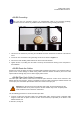
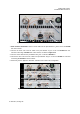
4.3 HOST UNIT INSTALLATION
Danger: Wet conditions increase the potential for receiving an electrical shock when
installing or using electrical power equipment. To avoid electrical shock, never install or use
the electrical equipment in a wet location.
Warning: Verify that the Unit has been ground with an earth-bonding cable to the grounding
connector.
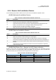
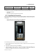
4.3.1 Host Unit Installation Overview
The installation of the Host Unit consists of the following steps:
Table 4-6. Host Unit Installation Overview
Step Operation Type Operation Action
1 ELECTRICAL
VERIFY THAT THE UNIT IS GROUNDED
2 ELECTRICAL
CONFIRM THAT THE DC POWER CABLE IS INSTALLED AND
SECURE
3 ELECTRICAL INSTALL THE BIU AND FIU MODULES
4 ELECTRICAL INSTALL THE ALARM CONNECTORS (Optional)
5 ELECTRICAL CONNECT THE BIU AND FIU
6
ELECTRICAL
CONFIRM THAT THE POI AND FAN (Opt. Equip.) ARE
CONNECTED
7 ELECTRICAL
CONNECT OPTIONAL EQUIPMENT TO THE BIU (if present)
8
ELECTRICAL CONNECT THE FIBER OPTIC CABLES
9
INSTALLATION
REVIEW
CONFIRM THE ELECTRICAL INSTALLATION, TABLE 4-10
HOST UNIT ELECTRICAL INSTALLATION CHECKLIST
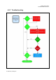
10 TROUBLESHOOTING INSTALLATION TROUBLESHOOTING GUIDE
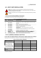
4.3.2 Installation Hardware And Tools
The Host Units may be shipped individually or shipped factory pre-installed in optional cabinets. Table 4-7
lists the cables and hardware provided by the manufacturer. Additional hardware may be needed,
depending on the site requirements, and may be ordered through Customer Service (Section 6).
Table 4-7. Host Unit Cables and Hardware
Single Host Unit
Hardware and Fasteners
Customer Install
Factory Install
Rec'd
1
1
CABINET (Optional)
HU DC POWER CABLE
ALARM CONNECTORS
8
3
4
FIU-S INTERFACE CABLE
FIU-NS INTERFACE CABLE
GROUNDING CABLES
1
POI GROUNDING CABLE
(Optional)
1