
User's Manual

mBSC DAS System
Installation Manual Issue 3
©2009‐2011,BTIPage36
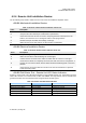
LED Indicator Colors Cycles
Test the LED Red and Green Blink 1 flash per second
Master RU Fiber Alarm Red Fast Blink 2 times per second
mRU and sRU Comm Fail Red and Green Blink 1 time per second
PA/LNA shutdown or Other Red Fast Blink 2 times per second
Normal Operation Green Blink 1 times per second
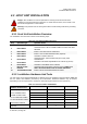
4.2.6 Remote Unit Installation Review
Use the following steps listed in Tables 4-3 and 4-4 to review the installation completion status
4.2.6.1 Mechanical Installation Review
Table 4-4. Remote Unit Mechanical Installation Check Lists
Items Description
1 Confirm that the Unit is mounted firmly and is stable.
2 Verify that the Unit is affixed per manufacturer's specifications.
3
Check that all screws and nuts are secure, that spring washers sit flush upon the flat
washers, and that there are no missing flat washers and spring washers.
4 Examine each part and cable for breakage or damage.
5 Make sure the Unit is clean and free of dust and other contaminants
4.2.6.2 Electrical Installation Review
Table 4-5. Remote Unit Electrical Installation Check List
Items Description
1 Verify that the grounding cable is secure.
2 Make sure that all the cable sheathings are not damaged.
3 Confirm that the connection to the cables are stable and are not loose or damaged.
Check that the cables are completely connected, but make sure there is enough slack, if
4 needed. Do not cross the cables and the cables should be bundled together in the same
direction.
5
Check that the connected cables are not bent more than the manufacturer's specified
maximum bending radius.
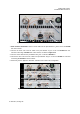
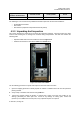
4.2.6.3 Field Status Test - Remote Unit LED Status Indicators
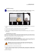
Perform a visual review of the LED Status indicators on the installed Remote Unit. The Remote Unit (RU)
status LED consists of a bi-colored LED of RED and GREEN. The high intensity LED is viewable from
ground level under most circumstances when using the BTI RU shroud system.
Table 4-6. Remote Unit LED Status Indicators