
User's Manual

mBSC DAS System
Installation Manual Issue 3
©2009‐2011,BTIPage34
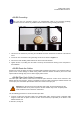
2. Secure the cable between the AC power port and the AC power junction box. Leave sufficient slack in
the cable to allow it to be easily connected and disconnected from the AC power port.
3. Install any AC power supply wires that may be required between the AC junction box and the AC
circuit breaker box.
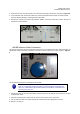
4. At the AC circuit breaker box, connect the AC power supply load wire to the circuit breaker.
5. Place the circuit breaker in the ON position and then test the connected end of the AC power cable for
proper voltage levels and correct polarity.
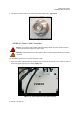
6. When testing is complete, PLACE THE CIRCUIT BREAKER IN THE OFF POSITION.
Danger: To avoid serious personal injury and equipment damage, always turn the AC
power off on the circuit breaker before connecting the any power cable to the AC power
port.
7. Connect the power cable connector to the AC power port labeled “POWER”.
8. Tighten the coupling nut.
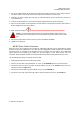
4.2.5.7 Slave Cable
Connection
When two RU or more enclosures are installed for supporting multi-band. One is designated the Master
Remote Unit and each additional RU, up to two Units, are designated as slave Remote Units. The Master
and slave Unit(s) is specified by the frequency band. The Master Unit will separate the bi-directional
signal related to the frequency and provide the RF input signal to each slave Remote Unit. The
connection between Master and Slave is interfaced with the RF cable provided with the Remote Units.
Use the following procedure to install the antenna cable:
1. All designated slave RUs arrive with two RF cables.
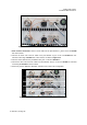
2. Connect one RF cable to the port labeled “TX_OUT” on the MASTER Remote Unit User Interface.
3. Connect the other end of the RF cable to the port labeled “TX_IN” on the SLAVE Remote Unit User
Interface as shown in Figure 4-12.
4. Connect the second cable to the port labeled "RX_IN" on the MASTER RU.
5. Connect the other end of the second RF cable to the port labeled "RX_OUT on the SLAVE RU.