
User's Manual

mBSC DAS System
Installation Manual Issue 3
©2009‐2011,BTIPage32
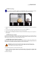
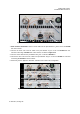
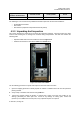
2. Route the free end of the drop cable to the enclosure through the junction box as shown in Figure 4-8.
3. Leave sufficient slack to allow the cable to be connected and disconnected from the enclosure fiber
optic port without bending or crimping the fiber optic cable.
4. Remove the cap from the interface port labeled "FIBER". Connect the fiber optic cable to the port on
the bottom of the enclosure.
Figure 4-8. Junction Box
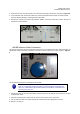
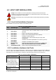
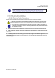
4.2.5.5 Antenna Cable Connection
The antenna feed line(s) must be routed from the antenna to each Remote Unit. The cable must have the
appropriate antenna connector termination to connect to the RU antenna port (ANT), shown in Figure 4-
9.
Figure 4-9. Antenna port
Use the following procedure to install the antenna cable:
NOTE: When using multiple RU enclosures to support more than one RF band,
each RU is supporting a different frequency. When routing the coaxial antenna
cable, it is critical that the appropriate frequency band cable be connected to the
same frequency type RU.
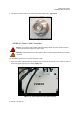
1. Remove the dust cap from the DIN female connector located on the bottom of the enclosure. The port
is labeled with “ANT”.
2. Route the coaxial antenna cables from the antenna to the bottom of the enclosures.
3. Cut the antenna cable to the required length and terminate with the appropriate connector.