
User's Manual

mBSC DAS System
Installation Manual Issue 3
©2009‐2011,BTIPage31
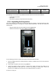
4.2.5.2 Grounding
The Unit must be grounded. Connect an earth-bonding cable to the provided grounding
connection. Do not connect any additional external devices to the grounding connection.
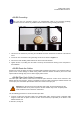
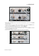
Figure 4-7. Grounding Connection
1. Uncover the RU interface by removing the Vandalism Protective Shield from the bottom of the Shroud
Cover.
2. Loosen the hex nut located on the grounding connection as shown in Figure 4-7.
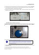
3. Connect the earth-bonding cable between the two lock and flat washers.
4. Tighten the hex nut, making sure the cable is securely connected before moving to the next phase of
the installation.
4.2.5.3 Route the Cables
Prepare and route all cables according to standard field installation procedures. Care should be taken to
prevent wear or field damage to cables during install. Particular attention should be paid to the Fiber
Optics Cable as damage may occur if cable is tightly coiled or bent.
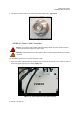
4.2.5.4 Fiber Optic Cable Connection
One fiber optic cable must be routed from an external splice enclosure or fiber access terminal to the
Master Remote Unit enclosure. The RU is equipped so only one cable is required per Master Remote Unit
for the optic port. A hardened optical E2000 connector is used for the optic port.
Warning: Do not look into the end of the fiber optic cable. Do not look directly into the
optical transmitter of any Unit or exposure to laser radiation may result. An optical power
meter should be used to check the active fibers.
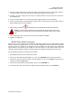
Use the following procedure to connect the fiber optic cable:
1. Connect or splice the drop Fiber cable to the outside plant cable. Verify that there is sufficient cable
length to reach from the splice enclosure or fiber access terminal (not provided) to the bottom of the
Master Remote Unit