
User's Manual

mBSC DAS System
Installation Manual Issue 3
©2009‐2011,BTIPage23
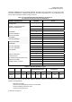
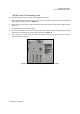
Hardware and Fasteners Quantity Rec'd
1
MOUNTING PANEL
(Configurable)
I-BEAM or U-BEAM/CHANNEL
MOUNTING BRACKETS
2
SHROUD COVER
1
8
8
M5 SCREW
M5 LOCK WASHER
M5 FLAT WASHER
8
8
8
M6 SCREW
M6 LOCK WASHER
M6 FLAT WASHER
8
8
8
8
M8 SCREW
M8 LOCK WASHER
M8 FLAT WASHER
M12 SCREW
4
M12 LOCK WASHER
4
4
1
2
1
M12 FLAT WASHER
JUNCTION BOX
RF CABLE (Designated Slave Unit)
FIBER OPTIC COWL
POWER CABLE (10 FEET)
1
FAN CONNECTOR (OPTIONAL)
1
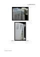
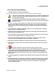
installation. Table 4-2 lists the mounting hardware provided by the manufacturer for a BTI non-custom
pole mount installation kit. Additional hardware may be needed, depending on the site requirements, and
may be ordered through Customer Service (Section 6).
Table 4-2. Single-Band RU Mounting Hardware and Fasteners
for a BTI non-custom pole mount installation kit
Table 4-3. Specified Hardware Torque
Type Screws Hex Nuts Spacers
Spring/Lock Washers
Spacers
Flat Washers
Thread M5 M8 M12 M5 M8 M12 M5 M8 M12
Specified
Torques
(lb. - ft.)
2
12
40
2
12
40
2
12
40
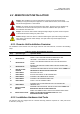
The following is a list of tools and any additional materials required for mounting every Single-Band
Remote Unit configuration:
•
DIN male connectors
•
Tool kit for attaching DIN connectors to coaxial cable
•
Tools for installing exterior AC circuit
•
Tools for securing M5 screw