
User's Manual

mBSC DAS System
Installation Manual Issue 3
©2009‐2011,BTIPage17
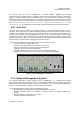
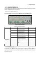
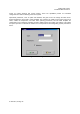
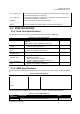
Figure 3-7. NMS Command Console
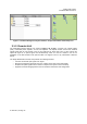
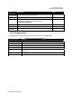
Table 3-2. Default Parameter Values
Menu
Parameter Name Default Value
System Parameter SNMP No
User Manager Name: Manager; Password: 1; Level: Supervisor
User User Name: User; Password: 1; Level: Observer
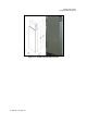
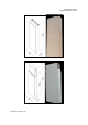
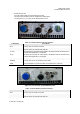
3.2.3 Remote Unit Interface
The interface of the Remote Unit consists of connectors and LEDs that are located on the bottom of the
RU enclosure. The Master RU user interface points are indicated in Figure 3-8 and Table 3-3. The Slave
RU user interface points are indicated in Figure 3-9 and Table 3-4.
Remote Units are classified as either MASTER or SLAVE. Master and Slave Units have exactly the same
mechanical dimensions. Functionality is the main difference as the MASTER Remote Unit has the
connection for the fiber optic cable. For supporting multiple bands, only the MASTER Remote Unit needs
to have the fiber optic connection with the Host Unit. Other Remote Units are interfaced with SLAVE ports
for receiving RF downlink signal and sending RF uplink signal with the Master Remote Unit.
•
MASTER Remote Unit:
•
Has the Fiber Optic Cable connection with the Host Unit
•
Provides the RF downlink signal to the SLAVE Remote Unit through “TX_IN” or “TX_OUT” port.
•
Receives the RF uplink signal from the SLAVE Remote Unit “RF_IN” or “RF_OUT” port.