
User's Manual

mBSC DAS System
Installation Manual Issue 3
©2009‐2011,BTIPage15
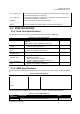
Module Name Port Name Description Remark
TX1, TX2 Downlink interface ports to be
connected to BIU output
RF signal
RX1, RX2 Uplink interface ports to be
connected to BIU input
RF signal
Fiber 1, Fiber 2 Fiber optic interface ports to be
connected to the RU
Optical signal
E9111, E9111-2 The RX coupling uplink signal for
LMU (TDOA location only)
RF signal
E9111, E9111-2 The RX coupling uplink signal for
LMU (TDOA Location only)
RF signal
FIU-S/FIU-NS
E9111, E9111-2 The RX coupling uplink signal for
LMU (TDOA Location only)
RF signal
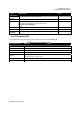
TX1, TX2, TX3, TX4
Input signals from the BTS to
provide the combined downlink
signal to FIUs
RF signal
RX1, RX2, RX3, RX4 The combined uplink signal from
FIUs
RF signal
TX1 and TX2 out Downlink RF interface to FIU RF signal
BIU-ND/BIU-D
RX1, RX2, RX3, and
RX4 out
Uplink RF interface from the FIU RF signal
3.2 USER INTERFACE
The user interface for each segment of the mBSC DAS System is designed to provide the most efficient
interaction, installation and ease of use for the user.
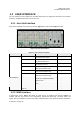
3.2.1 Host Unit Interface
Each interface module of the Host Unit, shown in Figure 3-5, is described in Table 3-1 below.
Figure 3-5. Host Unit Interface
Table 3-1. Host Unit User Interface
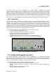
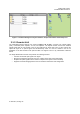
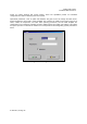
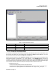
3.2.2 NMS Interface
A simple login access, Figure 3-6, allows for quick access. A graphical user interface, Figure 3-7,
provides real time user access to the configuration, performance monitoring, and alarm status. The
system also uses SNMPv2.0 protocol to transmit automated traps to the operator's Network Operations