User's Manual Part 1

section 06
page
29
40040005 rev. 000
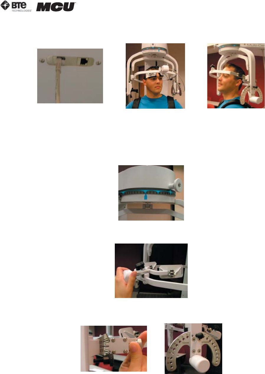
Step 13. Attach the RJ45 cable to the head brace being used and the RJ45 jack that is
closest to the front of the unit at the top of the MCU™ (Figure 6-71).
2. POSITIONING THE PATIENT FOR A 45 DEGREE ISOMETRIC LATERAL TEST
Step 8. Unlock the rotation pin, which is located at the top middle of the halo. If
you’re testing the patient’s left side, rotate the halo to 45 degrees right rotation, and
then lock the rotation pin. Rotate the halo to 45 degrees left rotation when testing the
patient’s right side (Figure 6-72). Note that the figures show a set-up for testing the
patient’s right side.
Step 9. Attach the head brace to the halo on the side being tested (Figure 6-73).
Step 10. Set the halo to 0 degrees with respect to the horizontal. Make sure the flexion/
extension angle is set to 0 degrees as well (Figure 6-74).
Step 11. Position the head brace against the patient’s head.
Step 12. Make fine adjustments to the seat to line up C5/C6 of the patient’s spine with
the pivot point of the halo (Figure 6-75).
Flexion Extension
Figure 6-71. MCU RJ45 Jack and Final 25
o
Isometric Flexion & Extension Set-ups
Figure 6-73. Attach Head Brace
Figure 6-74. Set halo angles
Figure 6-72. Halo Rotation of 45
o
Lateral


