User's Manual Part 1

page
24
section 06
40040005 rev. 000
1. POSITIONING THE PATIENT FOR A 25 DEGREE ISOMETRIC FLEXION/EXTENSION TEST
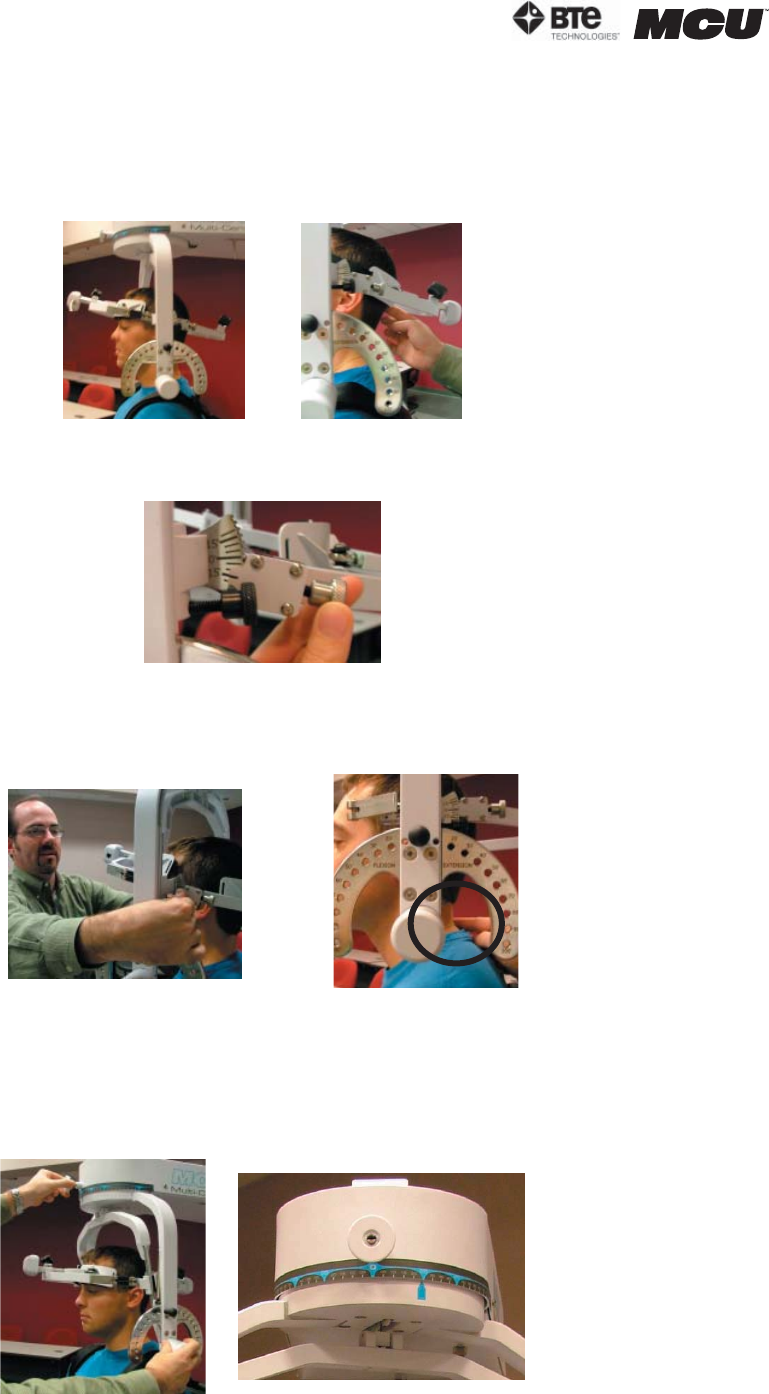
Step 8. For a flexion test, insert the front head brace. For an extension test, insert the
back head brace. Note that the bottom of the back brace is located at the external oc-
cipital protuberance (Figure 6-52).
Step 9. Set the halo to 15 degrees below the horizontal (Figure 6-53).
Step 10. Position the head brace against the patient’s head.
Step 11. Make fine adjustments to the seat to line up C5/C6 of the patient’s spine with
the pivot point of the halo (Figure 6-54).
Step 12. While holding onto the side of the halo, unlock the rotation pin, which is lo-
cated at the top middle of the halo. If you’re testing the patient’s left side, rotate the
halo 25 degrees right and then lock the rotation pin. Rotate the halo 25 degrees to the
left to test the patient’s right side (Figure 6-55).
Figure 6-54. Final Adjustments and Locating C5
Figure 6-53. Halo Angle
Location of
Back Brace
Figure 6-52. Initial Isometric Flexion
& Extension Set-up
Flexion Set-up
Unlock Rotation Pin
25
o
Right
Figure 6-55. Halo Rotation of 25
o


