User's Manual Part 1

page
10
section 06
40040005 rev. 000
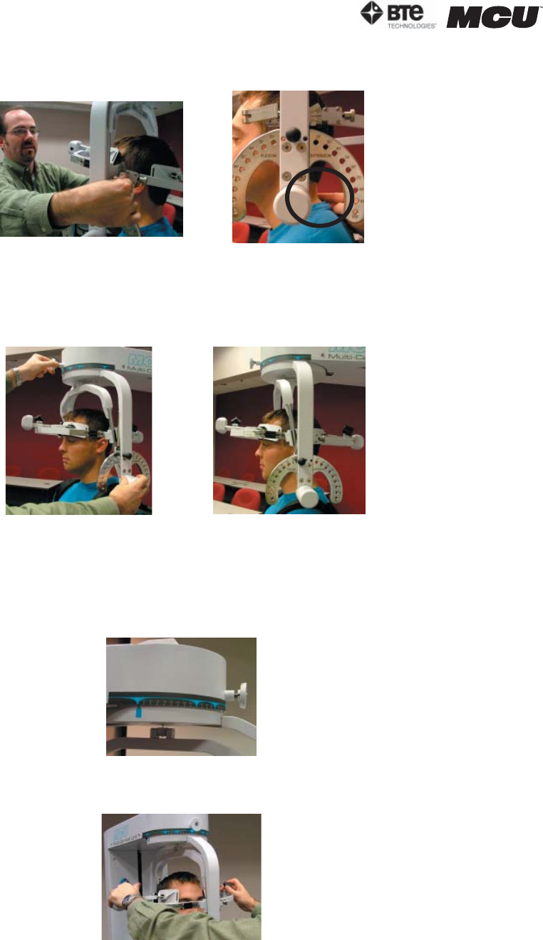
Step 11. Make fine adjustments to the seat to line up C5/C6 of the patient’s spine with
the pivot point of the halo (Figure 6-16).
Step 12. Firmly secure the patient’s head with the head braces.
Step 13. While holding onto the side of the halo, unlock the rotation pin, which is locat-
ed at the top middle of the halo, before performing the test (Figure 6-17).
Note that the RJ45 cable is not required for this test.
3. POSITIONING THE PATIENT FOR A ROM LATERAL FLEXION TEST
Step 8. Unlock the rotation pin and rotate the halo to 90 degrees right rotation. Lock
the rotation pin back into place (Figure 6-18).
Step 9. Insert both of the head braces in the halo (Figure 6-19).
Step 10. Set the halo to 0 degrees with respect to the horizontal. Make sure the flexion/
extension angle is set to 0 degrees as well (Figure 6-20).
Figure 6-16. Final Adjustments and Locating C5/C6
Figure 6-17. Unlocking Rotation Pin and Final
ROM L/R Rotation Set-up
Unlock Rotation Pin
Final Rotation Set-up
Figure 6-18. Halo at 90
o
Rotation
Figure 6-19. Attach Head Braces


