
Installation manual


Windsor Installation Manual - Issue C
-
49
-
Windsor Modem
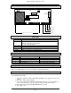
Mounting Positions
The Windsor modem can be mounted in 2 ways in a Windsor 500; either on PCB mounted
pillars or on above one of the ISB PCBs. In a Windsor 700 the modem can only be fitted
above one of the ISB PCBs.
Windsor modem fitted above
ISB PCB position 1, 2 or 3
(Windsor 500 or 700)
Windsor modem fitted on
PCB mounted pillars
(Windsor 500 only)
Windsor Modem
Status LEDs
LED Name Variant Function
DCD RX only Data Carrier Detect - on if carrier signal is detected from a
remote modem.
RTS RX only Ready To Send - used with CTS to perform data flow
control
DTR RX only Data Terminal Ready - on to indicate that the host is ready
for data communications
RI RX only Ringing Indicator - ringing has been detected
DSR RX only Data Set Ready - on to indicate a connection to the
telephone line
TXD RX only Transmit Data - data is being transmitted
RXD RX only Receive Data - data is being received.
CTS RX only Clear To Send - used with RTS to perform data flow
control
Comm Fail RX and panel on continuous if a call attempt fails
coincident with call progress tones
Comm OK RX and panel the last communication was successful and
flashes rapidly during the power up sequence
Exchange voltage is OK.
Power RX and panel DC power present
Off hook RX and panel modem is off hook
Comm Fail/OK RX and panel Rapid flashing indicates modem power up sequence
1
2
3