
Installation manual


Windsor Installation Manual - Issue C
-
47
-
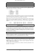
BC
TB
B
GND
A
TA
Modem Terminal Block Ancillary Equipment
BC Blue Wire of equipment
(and blue from pin4 of TE PLUG )
TB Red Wire of equipment
B
GND Green Wire of equipment
(and green from pin4 of TE PLUG )
A
TA White Wire of equipment
Figure 1.2
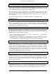
2. Windsor Modem Receiver (W73534)
Connection to the telephone network is made via the standard UK TE Plug. The following
connections to the modem’s RJ11 LINE socket are required, by using an RJ11 plug to
standard UK TE Plug adapter ( RJ11 sockets as viewed from above ).
LINE SOCKET HANDSET SOCKET
5 --
4 TA
3 TB
2 --
2 TA
3 A
4 B
5 TB
6 BC
1 GND
6 BC
1 GND
RJ11 PLUG Standard UK TE Plug
Line BC Blue - pin 4
Line TB no connection
Line B Red - pin 5
Line A Blue - pin 2
Line TA no connection
Line GND Green - pin3
RJ11 PLUG Standard UK TE
Socket
HSET BC Pin 4
HSET TA Pin 2
HSET TB Pin 5
HSET GND Pin 3
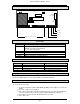
Series equipment
terminated in an RJ11
plug (figure 1.5) can be
directly inserted into the
modem’s handset socket
adapter is required for
series apparatus fitted
with a standard UK plug
(figure 1.4).
These can be purchased
from any computer or
telecomms wholesaler.
Figure 1.3