
Installation manual


Windsor Installation Manual - Issue C
-
46
-
The Windsor modem connects to the Windsor 500 or 700 with a ribbon cable. On a Windsor
500 it connects directly to the comms port without an RS232 interface adapter.
DC input Control panel interface
Audio inputs
EPROM
Status LEDs
PTT Connections
TB series connected apparatus ‘B’ wire
B PSTN ‘B’ wire
BC spur point only. For series apparatus
which use bell common
GND spur point only. For series
apparatus which use ground
A PSTN ‘A’ wire
TA series connected apparatus ‘A’ wire
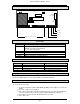
Windsor Modem
UK Telephone Network Connections
1. Windsor Modem Panel (W73535) and SmartDial Super (W73460)
Connection to the telephone network is made via the standard UK TE plug. The following
connections to the modem terminal block are required.
BC
TB
B
GND
A
TA
Modem Terminal Block TE PLUG ( ref. BS6312 Part1)
BC Blue - from pin 4
(if series equipment is to be connected)
TB
B Red - from pin 5
GND Green - from pin 3
(if series equipment to be connected)
A White - from pin 2
TA
Figure 1.1
Ancillary apparatus (handsets, answer machines, etc.) can be connected in series with the
modem by wiring the bare cables directly into the modem terminal block as shown in figure 1.1.
Up to three ancillary apparatus can be connected in parallel with each other providing the REN
of all equipment (including the modem) does not exceed 4 .