
Installation manual


Windsor 500 Installation Manual - Issue C
-
31
-
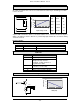
Concentrator
Connections
Connector Function Terminals
TB1 Control Panel Bus 1 - 12v
2 - Clock
3 - Data
4 - 0v
The screen terminal should be connected to
earth.
5 - Screen (optional)
PL1 Aux Power Output 1 - 12v
2 - 0v
Outputs supplied via fuse 1 3 - 12v
4 - 0v
PL2 Circuit 4 1 - 12v supplied from fuse 1
2 - detector input
Refer to diagram for EOL/NEOL connections.
3 - detector input
4 - 0v
PL3 Circuit 3 As PL2/Circuit 4 supplied from fuse 1
PL4 Circuit 2 As PL2/Circuit 4 supplied from fuse 1
PL5 Circuit 1 As PL2/Circuit 4 supplied from fuse 1
PL6 Aux Power Output 1 - 12v
2 - 0v
Outputs supplied via fuse 2
3 - 12v
4 - 0v
PL7 Circuit 5 As PL2/Circuit 4 supplied from fuse 2
PL8 Circuit 6 As PL2/Circuit 4 supplied from fuse 2
PL9 Circuit 7 As PL2/Circuit 4 supplied from fuse 2
PL10 Circuit 8 1 - 12v supplied from fuse 2
2 - detector input
Refer to diagram for EOL/NEOL connections.
3 - detector input
Day input is for use with an Excalibur sensor. LK4
4 - 0v
must be in the day position if day input is used.
5 - Day sensor input
PL11 Output 2 1 - +ve output
Output function is software programmable.
2 - +ve output
Refer to diagram for connections.
3 - -ve output
PL12 Output 3 8 output programmable daughter board
PL13 Output 1 1 - +ve output
Output function is software programmable.
2 - +ve output
Refer to diagram for connections.
3 - -ve output