
Installation manual


Windsor 500 Installation Manual - Issue C
-
23
-
Keypoint
Addressing
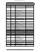
All keypoints are identified by a unique address which is set using links on the keypoint PCB.
The keypoint addresses must be in sequence from 1 up to the maximum number specified in
the System Size programming option.
UI LK4 LK3 LK2 LK1
0 / / / /
1 X X X X
2 X X X /
3 X X / X
4 X X / /
5 X / X X
6 X / X /
7 X / / X
8 X / / /
/ Link Fitted
X Link not fitted
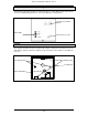
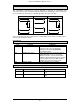
1 +12v
2 CLOCK
3 DATA
4 0V
5 -} Extension
6+} buzzer
The connections shown on TB1 are for a Windsor 500 keypoint. The order of connections on
a Windsor mark 1 keypoint is reversed. A Windsor 500 keypoint can be identified by the
backlit keypad and the circular electronic key socket.