
Installation manual


Windsor 500 Installation Manual - Issue C
-
18
-
Main Control Unit
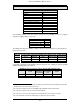
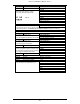
PCB Links
Link Function Comments
LK1 Battery connect When fitted the panel can be powered up on
battery power only.
When fitted deep discharge protection is
disabled.
LK2 ISB Fit the ISB link on LK2 if there are no ISB
PCBs fitted. (Fitted as default)
LK3 Engineer Keypad Fit the link if you require Windsor to
communicate with a keypad addressed as
KP0.
LK4 Power-up set If the link is fitted Windsor will return to the
set condition that the system was in when
power was removed. There will be a 1
minute delay to allow the sensors to
stabilise.
LK5 ISB Move the ISB link from LK2 to LK5 if there is
1 ISB PCB fitted.
LK6 ISB Move the ISB link from LK2/LK5 to LK6 if
there are 2 ISB PCBs fitted.
LK7 ISB Move the ISB link from LK2/LK5/LK6 to LK7
if there are 3 ISB PCBs fitted.
LK8 Off the Wall Tamper Off the wall tamper disable when fitted
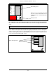
Main Control Unit
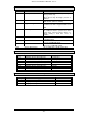
PCB Fuses
Fuse Type Function
Fuse 1 1A/250v, 20 mm, quick blow (F) Loudspeaker
Fuse 2 500 mA/250v, 20 mm, quick blow (F) UIB (keypads)
Fuse 3 1A/250v, 20 mm, quick blow (F) DGN (concentrators)
Fuse 4 1A/250v, 20 mm, quick blow (F) Aux. Power
Fuse 5 2.5A/250v, 20 mm, quick blow (F) Battery
Fuse 6 1A/250v, 20 mm, quick blow (F) Sounder
Fuse 7 1A/250v, 20 mm, quick blow (F) Strobe
mains 250v, 630mA, quick blow (F) Mains terminal block
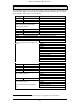
Main Control Unit
PCB Relays
Relay Type Function
RL1 Single pole changeover 2A maximum Battery disconnect
RL2 Single pole changeover 1A maximum Sounder
RL3 Single pole changeover 1A maximum Strobe