
Installation manual


Windsor 500 Installation Manual - Issue C
-
16
-
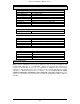
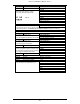
Connector Function Terminals
CON 11 Printer 1 No Connection
2 RXD
Serial output with 8 data bits, 1 stop bit
3 TXD
and no parity. Baud rate programmable
4 No Connection
5 0v
9 8 7 6 6 No connection
● ● ● ● Pin out 7 RTS
● ● ● ● ●
8 CTS
5 4 3 2 1 9 No connection
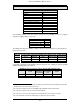
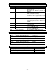
CON 13 Line Fault/Default 1 Line Fault (pull to 0v for fault condition)
2 Default Configuration (connect to 12v)
This input should only be used if a 3rd party communicator is being triggered from a TX or relay output.
In all versions prior to v3.00 fitting the default link will also clear the event log.
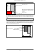
CON 14 Loudspeaker 1, 2 loudspeaker +, -
This output is protected by fuse 1.
Minimum load 16 ohms
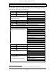
CON 15 Sounder 1 Normally Closed
This output is protected by fuse 6.
2 Normally Open
3 Common
This is the energised state (default). The sounder relay can be inverted by software.
CON 16 Strobe 1 Normally Closed
This output is protected by fuse 7.
2 Normally Open
3 Common
This is the energised state (default).
CON 17 Engineer Keypad 1 +12V
2 Clock
Fit LK3 if an engineer keypad is connected. If this
3 Data
link is fitted and no engineer keypad is connected
4 0V
then all keypads will respond more slowly.
CON 19 AC input Transformer secondary connector
CON 20 Battery Battery connectors
The battery is protected by fuse 5.
CON 21 Aux. power outputs 1 12v
2 12v
All 12v connections are protected by fuse 4.
3 12v
4 12v
5 0v
6 0v
7 0v
8 0v